Slt installation instructions (cont.) 2 – Bennett Marine SLT Self-Leveling Tabs User Manual
Page 5
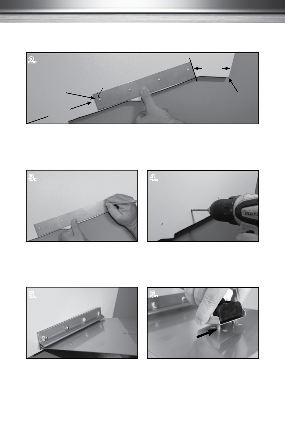
SLT Installation Instructions (cont.)
2.
Position the Tab. Using the backing plate, choose a location 3-4" from the chine. Maintain
a minimum of 8" from the centerline of your drive unit to the closest edge of the trim tab.
Align the bottom of the backing plate flush with the bottom of the transom. The hole pattern
on the backing plate should be closer to the top edge of the backing plate.
Mark the Pilot Holes. Using the same
backing plate as a template, mark the pilot
hole locations. Make sure the tabs can be
mounted in the same location on both sides.
3.
4.
Drill the Mounting Plate Holes, using a
5/32" drill bit. (For aluminum boats, use
#10-32 machine screws of an appropriate
length instead of the screws supplied.)
Install Tab and Hinge Assembly.
Dip screws in marine sealant before
inserting into pilot holes. Run the screws
in 3/4 of their length. Slide trim tab
between backing plate and hinge plate.
Now, tighten the screws.
5.
6.
Attach Actuator to Trim Tab. Start with the
center set of holes (Position #2), placing
the mounting bracket in between actuator
lower hinge and tab. Secure lower hinge with
included 1/4-20 x ¾" Philips Head machine
screws.
5
Hole pattern
closer to top edge
Chine
3"- 4"
At leas
t
8" fro
m
centerline of
drive
5/8"
#2