Bennett Marine EIC5000 Electronic Indicator Control User Manual
Bennett Marine Hardware
(EIC5000)
ELECTRONIC INDICATOR CONTROL
INSTALLATION AND OPERATION
INSTRUCTIONS
IMPORTANT - SPECIAL REQUIREMENTS:
System is voltage specific. Please make sure
•
you have a 12 or 24 volt EIC5000 depending
on your requirements.
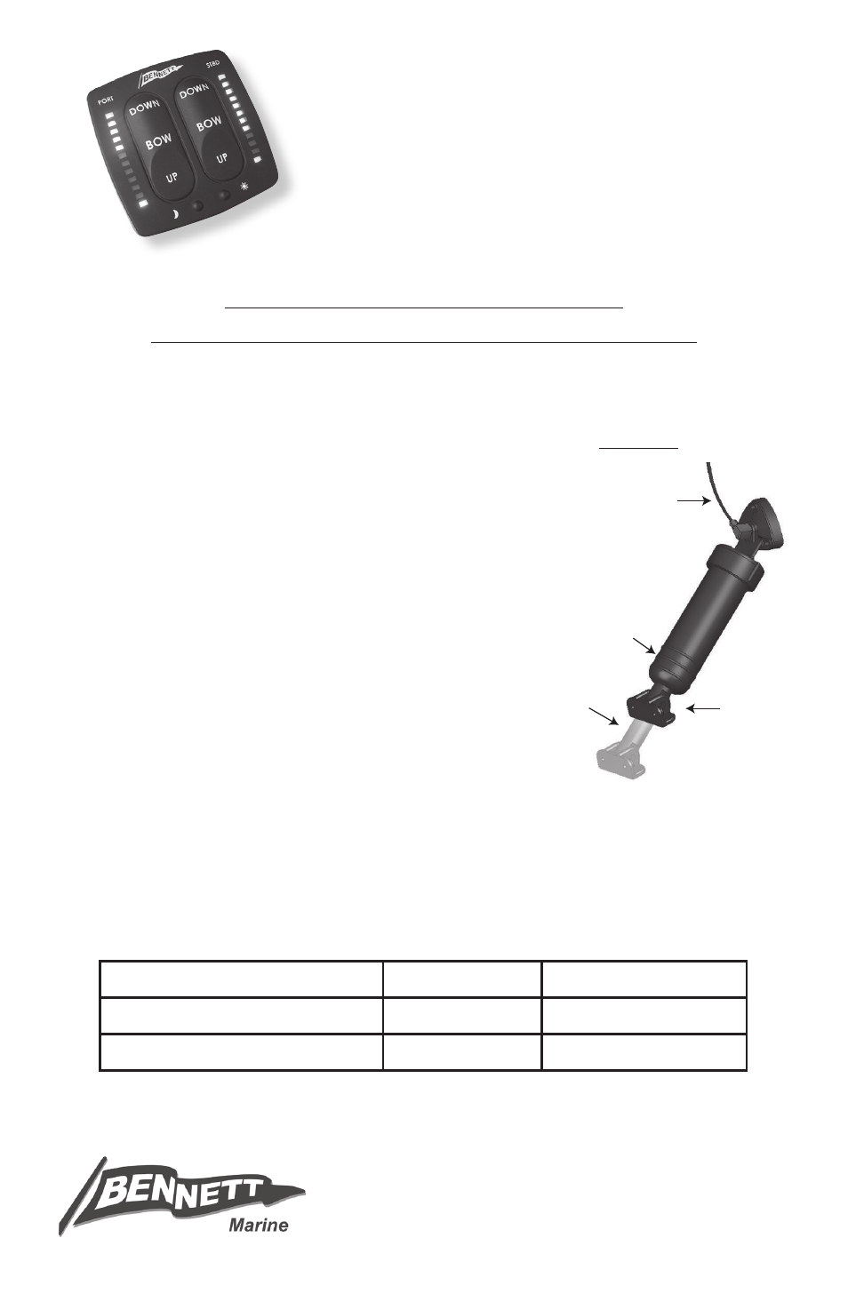
(SEE FIGURE 1)
•
Special sensor coils are required if:
- Actuator stroke is more than 2 ½" OR
- Less than 1" of piston shaft is exposed
when the actuator is fully retracted OR
- Actuator has external hydraulic connection
System will not work when actuator stroke is 1" or less
•
If installing in an M80 or M120 Sport Tab kit, your actuator will have three molded rings as
•
shown in Figure 1. Cut the metal rod to 6 11/16" as indicated by score mark (see enclosed
instruction sheet for cutting the rod).
BEFORE BEGINNING INSTALLATION:
READ INSTRUCTIONS COMPLETELY
MAKE SURE BATTERY POWER IS DISCONNECTED
TEST SYSTEM BEFORE PUTTING THE BOAT BACK IN THE WATER
FIGURE 1
7/16", 1/2" & 9/16" Wrench
Teflon Tape
Marine Grade Sealant
1/8", 3/16", 5/16" & 3/4" Drill Bit Wire Stripper
Vise Grips
2" Hole Saw
Electric Drill
Wire Cutter
REQUIREd TOOLS
KEEP THIS MANUAL WITH BOAT OWNER’S INFORMATION
Bennett Marine, Inc.
550 Jim Moran Blvd • Deerfield Beach, FL 33442
Phone: 954.427.1400 • Fax: 954.480.2897
Web: www.BennettTrimTabs.com
External Hydraulic
Tubing Connection
Three Rings
(cut rod only)
Less Than 1"
When Fully
Retracted
}
Less Than 1" or More
Than 2 ½" Total Stroke
}