Fault codes, Speed sensor troubleshooting – Bendix Commercial Vehicle Systems GEN 5 ABS User Manual
Page 25
25
Fault Codes
X2 (Black)
5
Speed Sensor (-) Right Steer
6
Speed Sensor (+) Right Steer
7
Speed Sensor (-) Left Steer
8
Speed Sensor (+) Left Steer
X3 (Green)
1
Speed Sensor (-) Left Rear
2
Speed Sensor (+) Left Rear
3
Speed Sensor (-) Right Rear
4
Speed Sensor (+) Right Rear
X4 (Brown)
3
Speed Sensor (-) Left Rear Rear
*
6-channel
4
Speed Sensor (+) Left Rear Rear
*
Only
5
Speed Sensor (-) Right Rear Rear
*
6
Speed Sensor (+) Right Rear Rear
*
Harness Connector
PIN
Circuit Description
Harness Connector
PIN
Circuit Description
B (6-Way)
4
Speed Sensor (+) Left Steer
5
Speed Sensor (-) Left Steer
C (9-Way)
4
Speed Sensor (+) Right Steer
5
Speed Sensor (-) Right Steer
D (15-Way)
5
Speed Sensor (+) Left Rear
6
Speed Sensor (-) Left Rear
8
Speed Sensor (+) Right Rear
9
Speed Sensor (-) Right Rear
E (12-Way)
5
Speed Sensor (+) Left Rear Rear
*
6-channel
6
Speed Sensor (-) Left Rear Rear
*
Only
8
Speed Sensor (+) Right Rear Rear
*
9
Speed Sensor (-) Right Rear Rear
*
*
Not Used On Basic System
*
Not Used On Basic System
X2 Black
X3 Green
X4 Brown
X1 Grey
7
8
9
10
11
12
6
5
4
3
2
1
7
8
9
10
11
12
6
5
4
3
2
1
7
8
9
10
11
12
6
5
4
3
2
1
7
8
9
10
11
12
6
5
4
3
2
1
10
11
12
7
8
9
4
5
6
1
2
3
10
11
12
13
14
15
13
14
15
16
17
18
7
8
9
4
5
6
1
2
3
10
11
12
7
8
9
4
5
6
1
2
3
7
8
9
4
5
6
1
2
3
4
5
6
1
2
3
A
B
C
D
E
TOP - Looking into harness connector
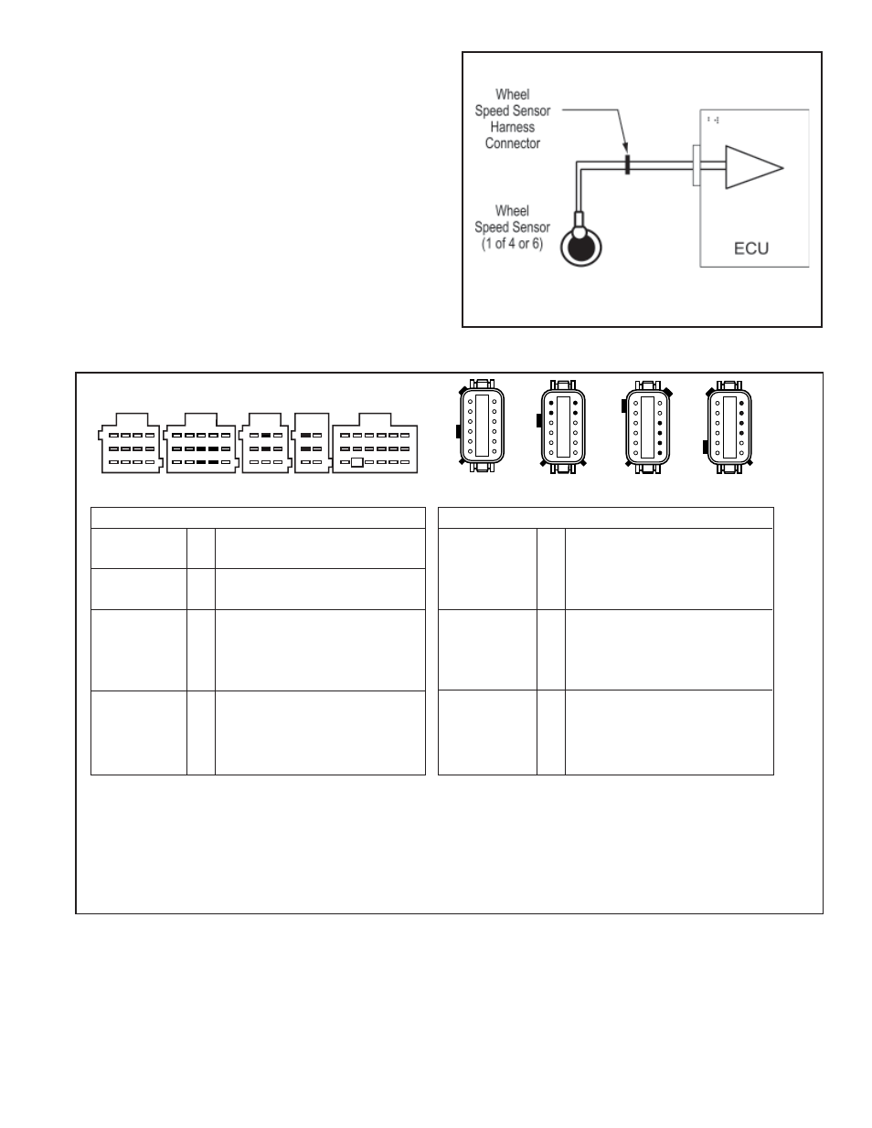
Speed Sensor Resistance Test
The correct resistance for the speed sensor circuit is between 950 ohms and 1900 ohms.
Measure resistance at the wheel location to check the speed sensor.
Measure resistance at the appropriate ECU harness connector pins to check the cable and speed sensor.
Note: Refer to the chart for pin identification.
FIGURE 24 - Wheel Speed Sensor Harness Circuit Descriptions and Resistance Test
FIGURE 23 - Typical Wheel Speed Sensor Circuit
Speed Sensor Troubleshooting
Follow the steps listed below to locate and correct sensor
related ABS trouble codes.
1. Access active trouble code(s) using either the Blink
Code procedure, with ServiceRanger or the Hand-held
Tester procedure.
2. Lookup the code description, the possible causes and
the repair procedures provided in this section.
3. Perform the recommended repair procedures.
4. After the repairs are completed, clear all codes and
check for any additional codes.
5. If a sensor related trouble code has occurred, a code
17•12 will remain in the system until the vehicle has
been driven.