Bendix Commercial Vehicle Systems GEN 5 ABS User Manual
Page 11
11
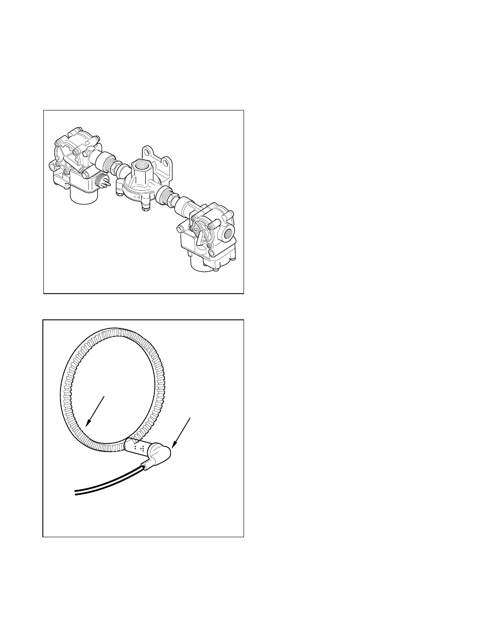
FIGURE 14 - Front Axle Module
Optional Front Axle Modules
An optional front axle module is available. It is an assembly
of two modulator valves and a quick release valve. Three
crack pressure settings are available:
•
0-1 PSIG
•
3-4 PSIG
•
6-8 PSIG.
FIGURE 15 - Sensor Assembly
Tone
Ring
Wheel End
Sensor
Standard
Wheel End Speed Sensor
Drive and Steer Axles
Right angle version shown
Straight version also available
Speed Sensors
Each wheel of an axle under direct ABS control is monitored
by a speed sensor. Speed sensors for drive axles and steer
axles may be different styles and installed in different
locations.
Wheel End Sensors
For most applications, Bendix ABS uses standard wheel
end sensors (see figure 15). The front sensor is accessible
on the inboard side of the steering knuckle. The rear drive
axle sensor is accessible by removing the wheel and drum
assembly.
Wheel-end sensors are conventional, single point, variable
reluctance sensors. These are often referred to as
"magnetic sensors" or "magnetic pickups." These sensors
consist of a rod or pole piece surrounded by a coil of wire.
A magnet is closely coupled to the pole piece and circulates
a magnetic field through the coil. As the teeth of the tone
ring rotate past the pole piece, the resistance (reluctance)
to the magnetic field varies. The variable reluctance causes
variations in the magnetic field which in turn induce a varying
voltage in the coils which are wound around the pole piece.
Some general characteristics of variable reluctance,
magnetic sensors are:
•
The output voltage decreases as the air
gap increases.
•
The output voltage increases with the speed of the teeth
past the pole piece.
•
The output voltage waveform is independent of the
direction of wheel rotation.
Wheel-End Sensors are protected with stainless steel metal
sheaths. They are designed to fit within beryllium-copper
friction sleeves which give them a self-adjustment feature.