Bendix Commercial Vehicle Systems GEN 5 ABS User Manual
Page 10
10
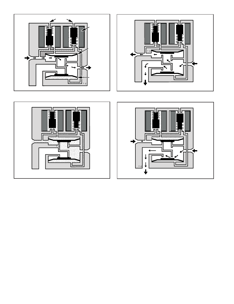
FIGURE 12 - ABS/ATC Hold
FIGURE 10 - Normal Apply and ABS/ATC Apply
FIGURE 13 - ABS/ATC Release
FIGURE 11 - Normal Release
Modulator Valve Operation Modes
1. Apply–Air flows straight through valve. Hold diaphragm
is vented to allow air flow. Inlet pressure feeds behind
release diaphragm to block the exhaust port. No
solenoids are activated.
2. Normal Release–With quick release function, hold
diaphragm is vented and there is no pressure at the
inlet port. Air is allowed to flow from outlet to inlet. Since
release diaphragm is not pressurized, air also flows out
the exhaust port. No solenoids are activated.
Outlet
Solenoid
Exhaust
Inlet
Vents
Release
Diaphragm
Hold
Diaphragm
Outlet
Exhaust
Inlet
Zero
Pressure
Outlet
Exhaust
Inlet
Outlet
Exhaust
Inlet
3. ABS/ATC Hold–The hold solenoid is activated. Both
diaphragms are pressurized. No air flows through the
valve.
4. ABS/ATC Release–Both solenoids are activated. The
hold diaphragm is pressurized, blocking the inlet air.
The release diaphragm is vented, allowing air to flow
from the outlet port back through the exhaust port.