Bendix Commercial Vehicle Systems WINGMAN ADVANCED SD User Manual
Page 33
33
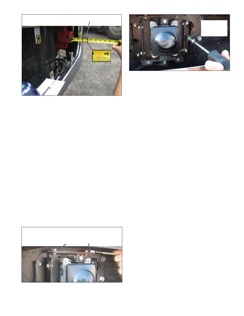
FIGURE 35 - LATERAL ALIGNMENT VERIFICATION
Laser Light Line
NOTE: The lateral alignment also can be checked with
Bendix ACom
®
Diagnostics (version 6.3 or higher). A
value between -0.8° and 0.8 ° is acceptable and the
system should operate normally. A value between
-0.8° to -1.3° OR 0.8° to 1.3° means the radar sensor is
misaligned and system performance will be degraded.
The service technician should align the radar sensor
using the procedures noted in this section.
If the value is less than (<) -1.3°, or greater than
(>) 1.3°, the system will typically issue a Diagnostic
Trouble Code. The service technician should align
the radar sensor laterally. A positive value means the
radar sensor should be aligned toward the driver side.
A negative value means the radar sensor should be
aligned towards the passenger side. The vehicle must
be driven at least 20 miles between adjustments. See
“Alignment Value” in Figure 17.
6.10 LATERAL ADJUSTMENT PROCEDURE
NOTE: Complete these steps only if a vertical adjustment
is necessary.
1. Loosen the four lateral position screws. DO NOT fully
remove them. See Figure 36.
Four Lateral Position Screws
[Two (2) on the top and two (2) on the bottom]
Loosen - Do Not Remove
FIGURE 36 - LATERAL POSITION SCREWS
Lateral
Adjustment
Screw
FIGURE 37 - LATERAL ADJUSTMENT
2. See Figure 37. Adjust the lateral adjustment screw until
the desired alignment is reached. DO NOT remove the
screws. Use steps 4 through 7 in Section 6.09: Check
Lateral Alignment
section to measure.
3 Retighten the four lateral position screws to hold the
desired alignment in place.
4. Recheck the lateral alignment as described above.
5. After the lateral alignment procedure is complete, if
there is an active misalignment DTC (codes 55, 56, or
57), reset the alignment value using the procedure in
Section 6.11.
6.11 RESET LATERAL ALIGNMENT VALUE
IN BENDIX
®
ACOM
®
DIAGNOSTICS
If a “radar alignment” diagnostic trouble code (DTC) was
logged, after repairs, the vehicle will need to be connected
to a PC with ACom Diagnostics software to reset the
“Alignment Value” to zero.
1. In ACom Diagnostics select Wingman Advanced on the
starter screen, and then select “Start with ECU.”
2. Select “Confi
g” on the Wingman Advanced Status
window.
3. Select “Modify” on the Confi guration Status window.
4. Select “Reset Alignment Value” in the Change
Confi guration box.
5. Select “Write” button in the dialogue box.
6. Clear the Bendix
®
Wingman
®
Advanced
™
system
trouble code using the procedure in Section
4.4: Clearing Diagnostic Trouble Codes (DTCs). Also,
s
ee Appendix D.
7. Close the ACom Diagnostics program and any open
windows.
8. Cycle the vehicle ignition.
6.12 REINSTALL THE PLASTIC COVER
With a slight force, push the cover onto the bracket so that
the plastic fasteners line up with the slots on the plastic
cover. Ensure the cover is secure over the radar sensor
assembly before driving the vehicle.