04 radar sensor alignment, 05 cover removal, 06 bendix – Bendix Commercial Vehicle Systems WINGMAN ADVANCED SD User Manual
Page 30: Alignment tools, 07 check the radar sensor vertical alignment
30
6.07.2 If the vehicle has an air suspension system, charge
the system and set it to “level” prior to carrying out an
radar sensor check or alignment procedure. If the
system is not charged, the vertical alignment will be off
and the Wingman Advanced system will not perform
correctly.
6.07.3 For an accurate check (and adjustment, if neces-
sary) of the vertical alignment, the vehicle needs to be
parked on a fl at, level surface.
NOTE: If the service technician is unable to park
the vehicle on a level
fl oor, a digital inclinometer
must be used to align the sensor vertically.
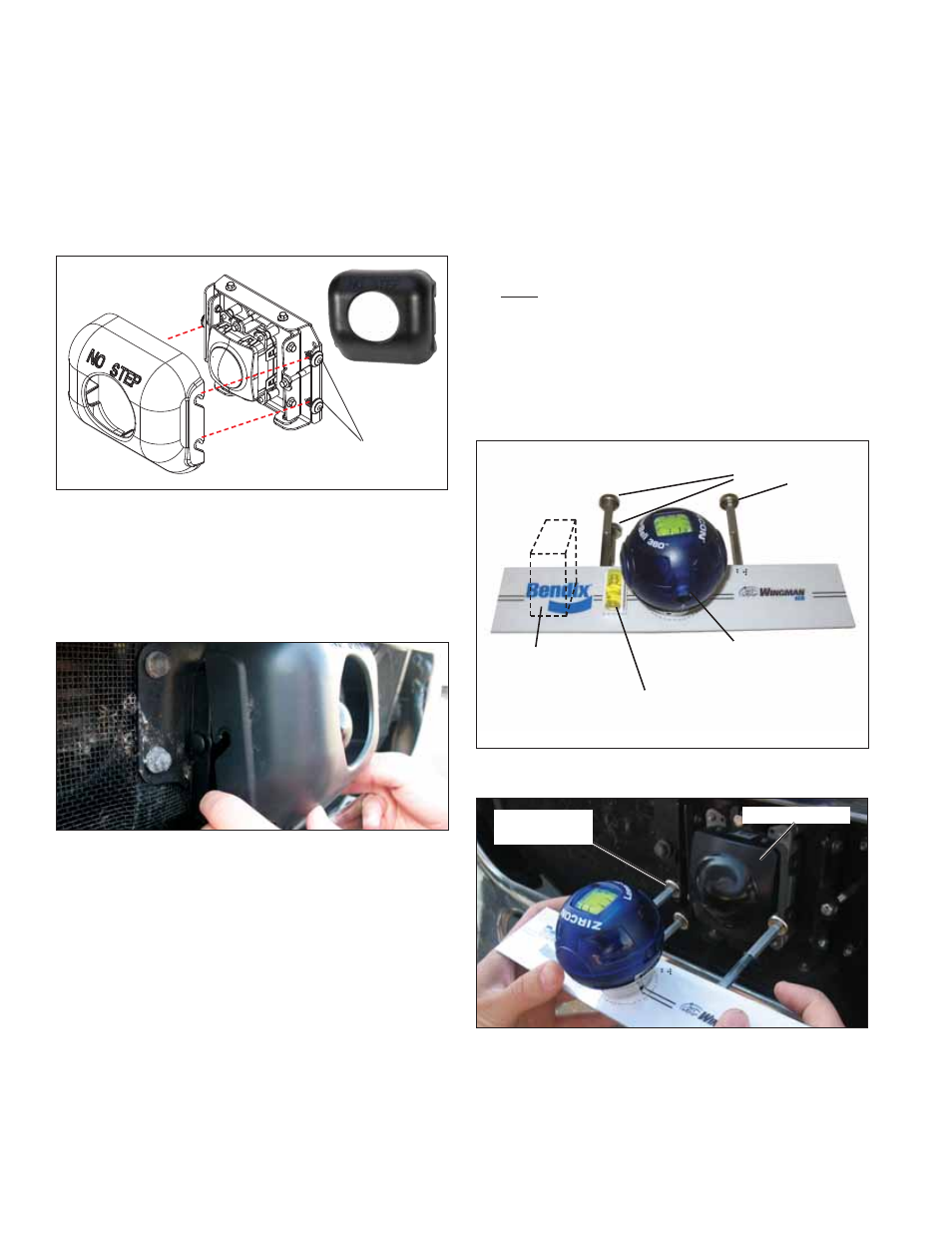
6.07.4. Position the alignment tool over the sensor so that
it straddles the sensor. Attach the alignment tool to the
bracket/sensor assembly using its magnet attachments.
Use the Lateral Alignment level to make sure that the
alignment tool is approximately horizontal width-wise.
See Figures 27 and 28.
Vertical Alignment Bubble
Level (Original design only)
Lateral Alignment Laser Level
(Original design shown)
Location
for Digital
Inclinometer
(Preferred
Method)
Magnetic
Attachments (3)
FIGURE 26 - BENDIX
®
ALIGNMENT TOOL (K041451 OR
K041227)
Radar Sensor
Magnetic
Attachments
FIGURE 27 - ATTACHING THE ALIGNMENT TOOL (SHOWS
TOOL K041451 OR K041227)
6.07.5 Check the vertical Alignment.
Using the standard tool K065284.
With the air
suspension charged and set to “level”, calibrate (“zero”)
the inclinometer on a horizontal section of the frame rail.
6.04 RADAR SENSOR ALIGNMENT
Accurate vertical and lateral alignment of the radar sensor
is critical for proper operation of Bendix
®
Wingman
®
Advanced
™
. Improper alignment will cause false warnings,
missed warnings and a diagnostic trouble code in the
system.
The radar sensor is mounted to the front of the vehicle
using an adjustable bracket. Use the following procedures
to align the radar sensor in its adjustable bracket:
Cover Fasteners Plastic
Tree Style (3)
FIGURE 24 - COVER AND PLACEMENT OVER RADAR
SENSOR ASSEMBLY
6.05 COVER REMOVAL
To remove the cover, use a slight force to pull the cover up
and away from the bracket. The three cover fasteners do
not need to be removed. See Figures 24 and 25.
FIGURE 25 - COVER REMOVAL
6.06 BENDIX
®
ALIGNMENT TOOLS
The Bendix
®
Alignment Tools (Bendix part nos: K065284,
K041451, or K041227) - available from Bendix parts outlets -
are used to align the radar sensor both vertically and laterally.
They fasten magnetically to the radar sensor assembly for
easy placement and removal. See Figures 26-28.
6.07 CHECK THE RADAR SENSOR
VERTICAL ALIGNMENT
See Section 6.06 for the Bendix
®
Alignment Tools available.
Additionally, Bendix strongly recommends that a digital
inclinometer should be when checking the vertical alignment
of the radar sensor.
6.07.1 Remove the cover as shown in Section 6.05: Cover
Removal.