Bendix Commercial Vehicle Systems WINGMAN ADVANCED SD User Manual
Page 23
23
4.4 CLEARING DIAGNOSTIC
TROUBLE CODES (DTCs)
This procedure must be used when troubleshooting the
diagnostic trouble codes shown in Table 6.
Clear the Wingman Advanced system Diagnostic Trouble
Codes (DTCs) using the Bendix
®
ACom
®
service tool. Click
the “Clear” button located on the “Read / Clear Fault Codes”
screen. Using ignition power only, power off the vehicle
for at least 15 seconds. Next start the engine and run it at
idle for at least 15 seconds.
Drive the vehicle and, on a test track or suitable section
of roadway, engage the cruise control to verify proper
operation.
If the error returns, call Bendix at 1-800-AIR-BRAKE for
assistance.
4.5 TROUBLESHOOTING DIAGNOSTIC
TROUBLE CODES: POWER SUPPLY
IGNITION VOLTAGE TOO LOW
Measure the ignition voltage under load. Ensure that the
ignition voltage is greater than 10 VDC (volts DC). Check
the vehicle battery and associated components. Inspect
for damaged wiring, damaged or corroded connectors and
loose connections. Check the condition of the fuse.
IGNITION VOLTAGE TOO HIGH
Measure the ignition voltage. Ensure that ignition voltage
is not greater than 16 VDC. Check the vehicle battery
and associated components. Inspect for damaged wiring,
damaged or corroded connectors and loose connections.
POWER SUPPLY TESTS
1. Take all measurements at the radar sensor harness
connector.
2. Place a load (e.g. 1157 stop lamp) across the supply
voltage and ground connection. Measure the voltage
with the load. The supply voltage on pin 8 to ground
should measure between 10 to 16 VDC (volts DC).
3. Check for damaged wiring, damaged or corroded
connectors and loose connections.
4. Check the condition of vehicle battery and associated
components. Ensure the connection to ground is
secure and tight.
5. Using the procedures described by the vehicle
manufacturer, check the alternator output for excessive
noise.
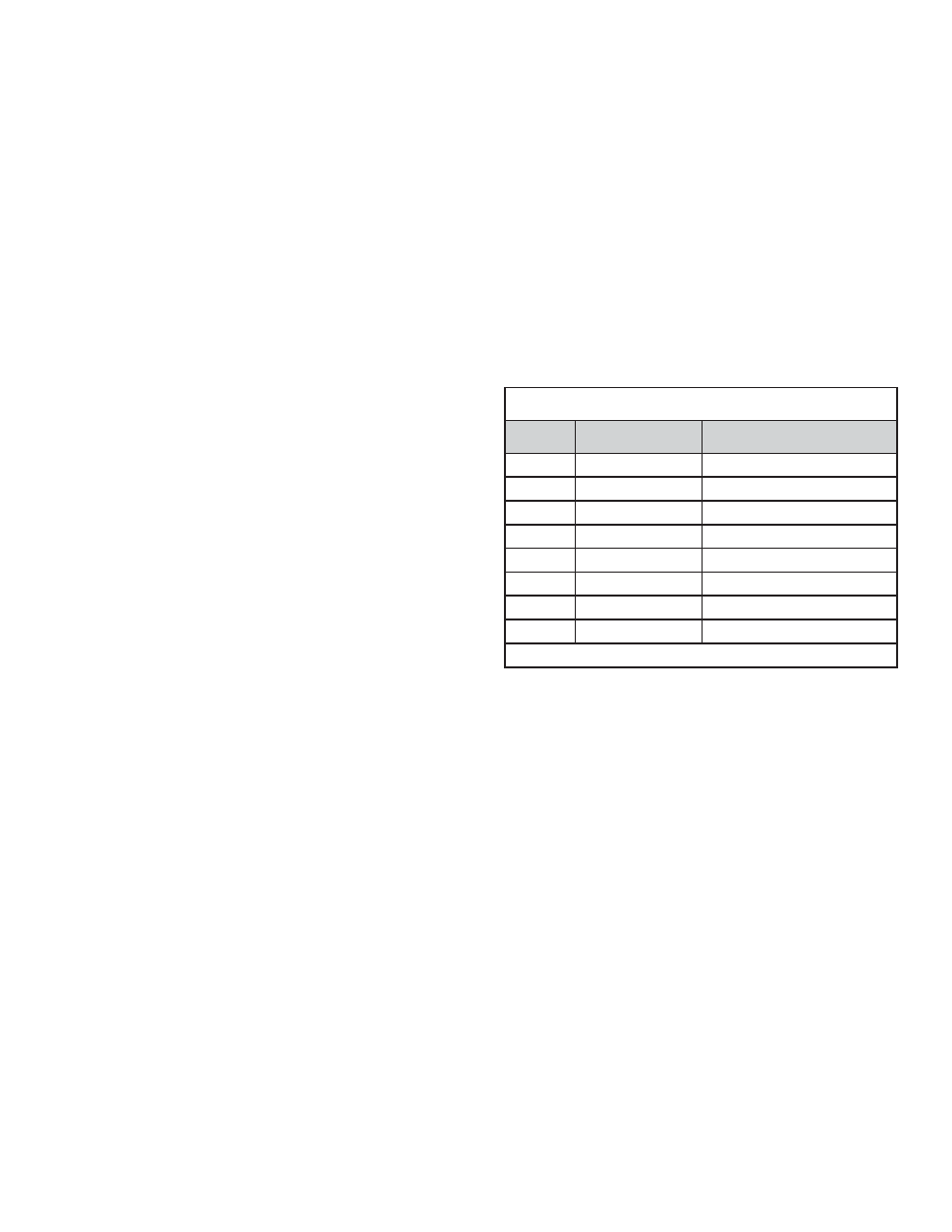
Power Supply Pin Codes (4.5)
Pin #
Designation
Description
1
GND (-)
Radar Sensor Ground
2
CAN-H
J1939 High
3
CAN-L
J1939 Low
4
NC
No Connection
5
NC
No Connection
6
NC
No Connection
7
NC
No Connection
8
IGN (+)
Supply Voltage
NOTE: View from pin side
TABLE 7 - POWER SUPPLY PIN CODES