Bendix Commercial Vehicle Systems TABS-6 ADVANCED MC SD SHEET User Manual
Page 21
21
How the Bendix
®
TRDU
™
Tool Operates
When the TRDU tool is plugged into the adapter — and the
adapter/TRDU tool is installed between the trailer connector
and the J560 connector of the towing vehicle that has the
ignition on — all the LEDs will illuminate, and the green
LED will flash 4 times to indicate communications have
been established.
If the ABS ECU has no active Diagnostic Trouble Codes
(DTCs), only the green LED will remain illuminated.
If the ABS ECU has at least one active DTC the TRDU
tool displays the first DTC by illuminating the red LEDs,
indicating the malfunctioning ABS component and its
location on the vehicle. (See Figure 13.)
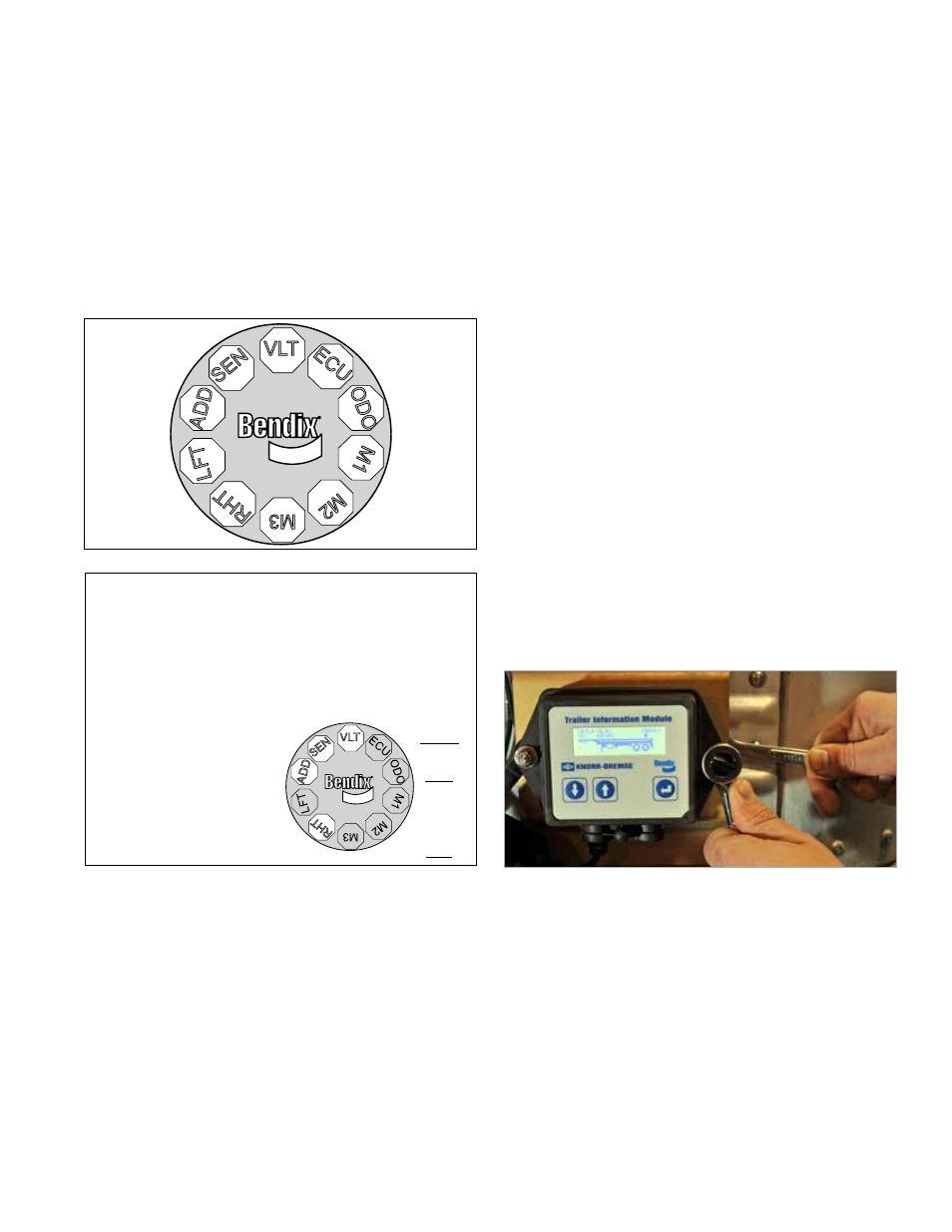
FIGURE 13 ‑ the bendix
®
tRdu
™
tool diSPlAY
LED Diagnostic Trouble Codes
VLT -
Power
ECU - ABS Controller
SEN - Wheel Speed
Sensor
MOD1 - Modulator 1
MOD2 - Modulator 2
MOD3 - Modulator 3
LFT -
Left
RHT ‑ Right
ADD - Additional
ODO - Odometer
Example: If the DTC
is "Right Additional
Sensor", the TRDU
™
tool
will display one green
and three red LEDs
LEDs
Green
VLT
Blue
ODO
All
others
are
Red
FIGURE 14 ‑ diAGnoStic tRouble codeS uSinG the
bendix
®
tRdu
™
tool
If there are multiple DTCs on the ABS system, the TRDU
tool will display one DTC first, then once that DTC has
been repaired and cleared, the next code will be displayed.
The TRDU tool repeatedly blinks out the mileage stored
once communications have been established. By counting
the sequence of blinks and/or strobes on the blue LED, the
odometer reading is given. See Section 10 for more details.
•
VLT (Flashing indicates either over- or under-voltage
condition)
To pinpoint the root cause and to ensure the system DTC is
properly corrected the first time, additional troubleshooting
may be necessary.
Note: When a TRDu tool is connected to a system with
a Bendix
®
TABs-6
™
Adv mC module, and has established
communications, the ECu will use the ABs indicator lamp
to blink codes for all active DTCs.
Bendix TRDU Tool Reset Function
The magnetic reset switch is located by the letter "B" in the
Bendix logo on the top of the TRDU tool. When a magnet
(with minimum of 30 gauss) is held over the switch for
less than 6 seconds the "clear DTCs" command is sent.
(If a magnet is not available, you may use a spare wheel
speed sensor, since its internal magnet will be sufficient.)
Additionally, it is recommended at the end of any inspection
that the technician switches off and restores the power to
the ABS ECU, and then re-checks the ABS indicator lamp
and TRDU tool to see if they indicate any remaining DTCs.
Bendix
®
Trailer Information Module
The Bendix Trailer Information Module is a display device
that combines the functionality of system diagnostics
with the ability to display and store other trailer‑related
information of value to an operator, driver or workshop.
Maximum benefit is obtained from the Trailer Information
Module functionality when it is mounted on the trailer so
that it is able to record events that occur during driving.
Alternatively, it may also be used as a workshop tool to
access diagnostic information or to check the configuration
or run an installation test. In both cases the Trailer
Information Module is connected to the J1939 EC5V TI
(CAN) connection of the auxiliary connector which supplies
the necessary information.
FIGURE 15 ‑ tRAileR inFoRmAtion module
AdditionAl SuPPoRt At
www.bendix.com
For the latest information, and for free downloads of literature
and the Bendix
®
ACom
®
diagnostics software, and its User
Guide, visit the Bendix website at www.bendix.com.
Bendix Technical Assistance Team
For direct personal technical support, call the Bendix
technical assistance team at
1‑800‑AIR‑BRAKE (1-800-
247-2725), Monday through Friday, 8:00 a.m. to 6:00 p.m.
EST.
Alternatively, you may e‑mail the Bendix Tech Team at: