Troubleshooting: system schematics, 4s/3m - side/axle control, Continued) – Bendix Commercial Vehicle Systems TABS-6 TRAILER ABS MODULE User Manual
Page 21: A b s, Right - “curb-side” left - “road-side
21
Trailer ABS
Module
WS-24
™
Wheel Speed Sensors
WS-24
™
Wheel Speed Sensors
SR-5
™
Trailer
Spring Brake
Valve
BR9235
™
Modulator
Relay Valve
TABS-6
“MOD1”
A B S
Tri-Axle Trailer
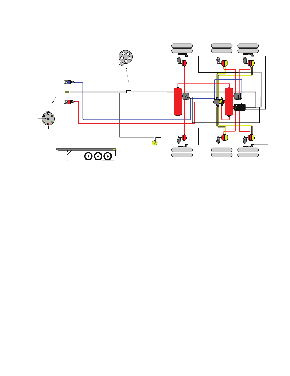
4S/3M - SIDE/AXLE CONTROL
Trailer
Chassis Harness
Trailer ABS
Pigtail Harness
5-PIN
CONNECTOR
Ignition
Power
Brake Light
Power
Ground
7-PIN
CONNECTOR
SUPPLY
LINE
CONTROL
LINE
A
Brake Light Power
B
Ignition Power
C
NC
D
Warning Lamp
E
Ground
C
E
B
A
D
ABS Light
TA
B
S
“MOD2”
"SR"
"SL"
"SAR"
"SAL"
BR9235
™
“MOD3”
Right -
“Curb-Side”
Left -
“Road-Side”
Troubleshooting: System Schematics
(continued)
Installation Guidelines for the TABS-6 4S/3M Side/Axle ABS Confi guration:
• MOD1 (TABS-6 ABS Unit) controls the left “road-side” wheel(s) of a primary axle(s).
• MOD2 (BR9235
™
Modulator Unit) controls the right “curb-side” wheel(s) of a primary axle(s).
• MOD3 (BR9235
™
Modulator Unit) controls the wheels of an additional axle(s).
• SL & SR (Primary Sensors) senses wheels on the primary axle (always on the ground) that MOD1
controls, and are connected to the dedicated 2-pin connector on the TABS-6 ECU.
• SAL & SAR (Additional Sensors) senses the wheels that MOD3 controls, and are connected to the
18-pin connector on the TABS-6 ECU.
• For lift axle applications, MOD3 controls the wheels for the lift-able axle.