Part two: installation – Bally Refrigerated Boxes Walk-In Installation Manual User Manual
Page 4
UPDATED: 6/2014
Instruction Manual IM-268-11 2014© Bally Refrigerated Boxes, Inc. 4
Part Two: Installation
1.
Positioning
Walk-Ins erected near existing building walls must be positioned
with minimum 2” clearance to allow for air circulation and prevent
possible condensation on the exterior surface of the Walk-In. It is
important to check that the building’s walls are square and plumb, if
they are not this will have to be taken into account when erecting
the sidewalls. If refrigeration and coil drain tubing is to be run
between Walk-In and building wall allow space for installation.
Check for overhead objects that will intrude the Walk-Ins height.
Depending on temperature and humidity, air circulation may be
needed to equalize the air temperature and the panel surface
temperature above the dew point; this is usually required in a dead
air space and high humidity environment.
2.
Walk-Ins with Screeds
If any part of your Walk-In employs screeds, lock the screeds to the
bottoms of the panels before placing any vertical panels. Vinyl floor
screeds are anchored to concrete in less-floor Walk-Ins via drive pins
with sleeve anchors provided by Bally. Drill into the concrete or
other surface with a masonry bit. When using vinyl screeds, shim to
make sure panels are level inside the screed. If the Walk-In is being
installed on quarry tile, floor holes may be drilled to hit tile seams.
Check all dimensions before proceeding.
3.
Assembly of Less-Floor Walk-Ins
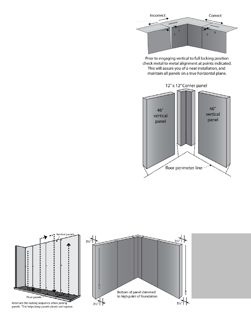
A. After you have checked that the building floor is level, use a
transient or builders level to find the highest point on the
perimeter. Position the first 12” x 12” corner to be level with the
high point. Begin at corner and align panels at the top. See Figure 4.
B. Position a vertical panel to the right and left of the corner panel (as
per Plan View) and flush with the perimeter line. Once properly
aligned, fully engage all vertical-to-vertical locks. See Figure 5.
C. Level panels to the perimeter high point and check for plumb with a 48” spirit level. (Panels over 10’ high use a plumb bob.) See
Figure 7.
D. As each panel is installed, check to make sure it’s plumb and level. If the panel is not plumb, shim to adjust for plumb. Making the
same check down the panel’s leading edge shows whether it’s level along the top or not. If not adjust accordingly.
E. Continue installing vertical panels in the same manner, periodically checking to make sure that panels remain plumb and level. See
Figure 6 (staggered locking sequence).
F. When enough vertical panels are set to accept the installation of the first ceiling and end panel, begin assembly of the ceiling
panels. See Section 9 for method of installing remaining vertical and ceiling panels.
G. With installation complete, caulk the bases of the vertical panels where they meet the concrete floor.
Always check to
make sure that
each new panel is
level and plumb.
Figure 4
Figure 5
Figure 6
Figure 7