Setupsequence(continued) – Weidmuller PMX400TMP - Display instrument for control panel User Manual
Page 10
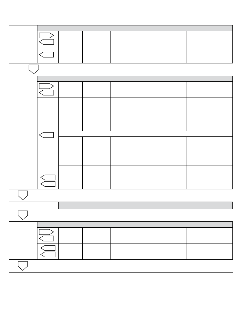
AL1-4
Alarms1-4enable/disablemenu
%.4
1(.
1 & 2
Select
A12y
A12n
Alarms one and two enabled
Alarms one and two disabled
Toggle
Accept
1(.
3 & 4
Select
A34y
A34n
Alarms three and four enabled
Alarms three and four disabled
Toggle
Accept
%.4
Press
PGM to skip to analogue output menu.
AL1
Alarmchannelsetupmenus(repeatedforeachenabledalarmchannel)
%.4
1(.
Coil state
A1nE
A1nd
Normally energised
Normally de-energised
Toggle
Accept
1(.
Alarm
type
A1=lO
a1=HI
a1=OC
A4=Sr
A4=gr
Low alarm
High alarm
Open circuit alarm (ch 1 only)
Siren alarm (ch 4 only)
Group alarm (ch 4 only)
Toggle
Accept
Note: the following settings are not shown for group siren or sensor break alarms
Setpoint
SP1=
50.0
Introduces setpoint value
Any value witin the display limits
-
Inc
-
Dec
Next
Accept
Deadband
db1=
10.0
Introduces deadband value
Any value within the display span
-
Inc
-
Dec
Next
Accept
Timer
delay
dl1=
Introduces timer delay
-
-
Next
%.4
1(.
0
(0s to 4200 s)
Inc
Dec Accept
1(.
AL2,AL3,AL4
AlarmChanneltwo,threeandfoursetupmenus
1(.
A-ALL
AllAlarmsSubmenu(resetmodeandsetpointsecuritysettings)
%.4
1(.
Reset
sequence
nor
reS
Automatic reset
Manual reset
Toggle
Accept
%.4
1(.
Setpoint
security
SECy
SECn
Change setup mode only
Change in run or setup mode
Toggle
Accept
1(.
SetupSequence(continued)