Vicor Full-chip PRM-RS Customer Board User Manual
Page 12
UG:009
vicorpower.com
Applications Engineering: 800 927.9474
Page 12
8.3.1 PRM – VTM Board, Non-isolated Remote Sense Setup
This is NOT the nominal configuration of the customer board and requires rework to implement.
1. Determine the maximum desired VTM module output trim voltage (R
22
fully clockwise).
2. Use Equation 1 to select the appropriate value for R
24
/R
29
. Obtain the closest 1% standard
value, size 1206 resistors for installation.
3. Remove R
40
.
4. Install R
24
and R
29
in the appropriate positions
5. Determine the type of VTM Customer Board to be used.
a. Type A:
i. Install single male-to-male header to X01 only.
ii. Connect PRM and VTM Customer Boards together as illustrated in Figure 11.
iii. Connect the VS+ test point to the VTM Board +OUT test point, and VS- test point
to the VTM Board –OUT test point through a twisted pair of wire
b. Type B:
i. Install dual male-to-male headers to X01 and X03
ii. Connect PRM and VTM Customer Boards together as illustrated in Figure 12.
iii. Verify connection from VS+ to VTM +OUT, and VS- to VTM -OUT
6. Connect a jumper between VTM –OUT and VTM –IN
7. Connect input source to the input lugs. Verify proper polarity. Set to 0 Volts or OFF before
connecting.
8. Connect VTM Board output to desired load using the output lugs. Set load to 0 Amps or OFF.
1.24k
R30
1.24k
R23
V s-
V s+
PRMO UT
V S+
V S-
TP10
TP11
R4 0
R24
R29
6
5
7
U09B
GND
OPEN
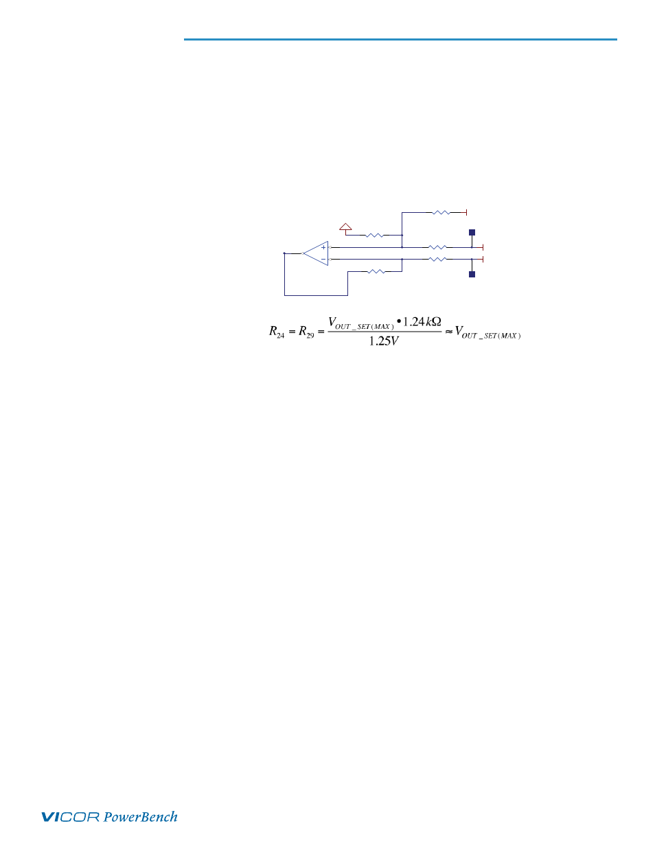
Figure 10: Remote Sense
Configuration
Equation 1
Where: V
OUT_SET(MAX)
is the maximum VTM output trim voltage
8.3 PRM
®
– VTM
®
Board Operation, Non-isolated Remote Sense
In this configuration, the PRM and VTM Customer Boards are connected together to form a
PRM / VTM pair and regulation is performed at the VTM module output. U09B is configured as a
differential amplifier with a gain set for the appropriate output voltage. R24 and R29 set the gain
and limit the maximum VTM output voltage based on Equation 1 assuming the trim pot (R22) is
fully clockwise.