Javelin i & ii power supply – Vicor Javelin II User Manual
Page 2
Javelin I & II Power Supply Operator’s Manual
Javelin I & II Power Supply
Power Factor Corrected AC-DC Switcher
Javelin I & II Power Supply “Quick Install” Instructions
The Javelin can be mounted at either of two sides (top or bottom).
Use #8-32 mounting screws. Maximum penetration should not exceed 0.21″ (5,33mm).
Maintain 2″ (50,8mm) clearance at either end for airflow.
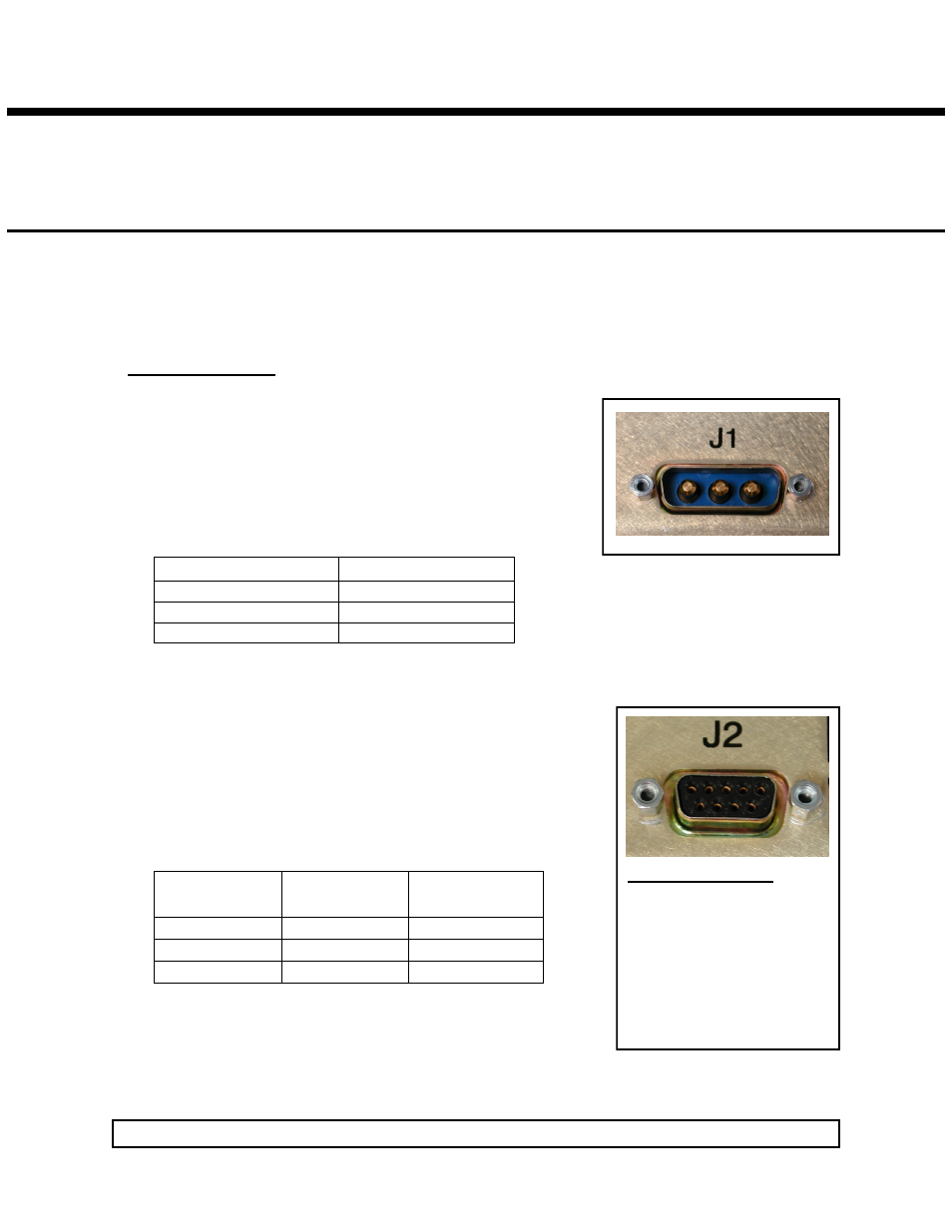
Input AC or DC power is applied to connector J1 using a 3W3 Power
Connector (Table 1).
To connect, use ITT/Cannon mating receptacle P/N DAM3W3SA197
with pins, P/N DM53744-6.
A fault-clearing device, such as a fuse or circuit breaker, with
maximum 15A rating at the power supply input is required for
safety agency compliance.
Single Phase
DC
A1 L1
A1 +
A2 L2/N
A2 –
A3 Earth Gnd
A3 Earth Gnd
Table 1. AC and DC Input Connections
Status/Control Connector (J2)
J2-1 and J2-9 are spare pins and are not used.
J2-2 and J2-4 are Signal Return pins.
J2-3 is +12V fan power.
J2-5 is VCC +5V @ 300mA.
J2-6 is AC Power OK (+5V = true).
J2-7 and J2-8 are used in conjunction according to the following table:
Input Connections
Input Connector (J1)
Mounting the Javelin Power Supply
J2-8
INHIBIT′
J2-7
ENABLE′
POWER SUPPLY
STATE
1
X
ON
0
0
ON
0
1
OFF
Table 2. Inhibit/Enable Logic Table
Use ITT/Cannon mating connector P/N DE9PK87 with Amp cover
shell P/N 205729-1.
Use 20-24 AWG stranded wire.
Rev. 05/11/2012 Mission Power Solutions (760) 631-6846 [email protected] Pg. 2
J2 Interface Pin Out
J2-1
Spare
J2-2 Signal Return
J2-3
Fan Power
J2-4
Signal Return
J2-5
VCC +5V @ 300mA
J2-6
AC Power OK
J2-7
PS Enable
J2-8
PS Inhibit
J2-9
Spare
1
5
6
9
A1 A2 A3