Installation and operation guidelines, Vi series, Mi series – Vicor ComPAC Family 50 to 600 Watt DC-DC Switchers User Manual
Page 6
Installation and Operation Guidelines
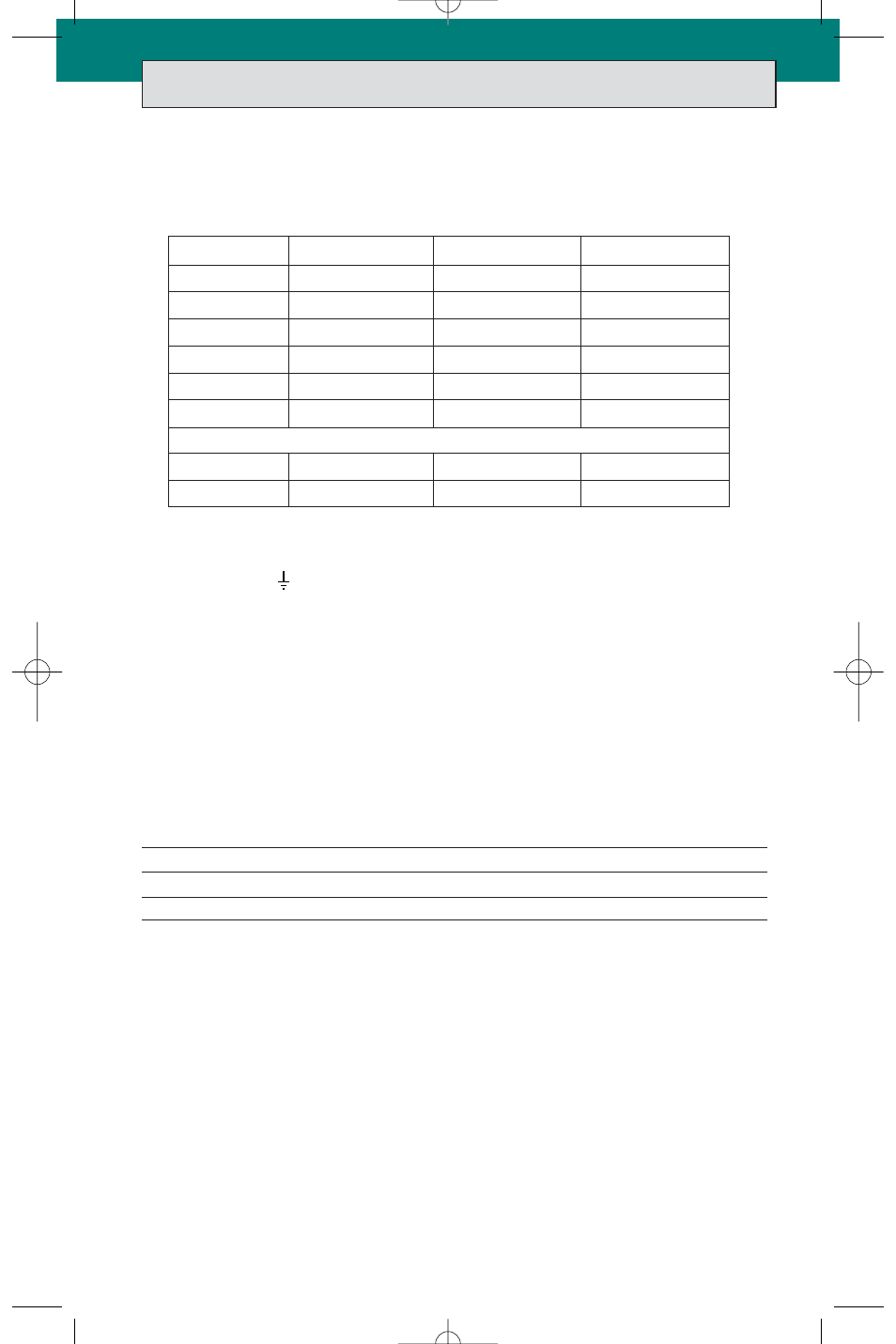
Input Line Fusing. The ComPAC must be fused externally. The table below lists the fuse
ratings for one-, two-, and three-up units (max. output 200, 400, and 600 Watts).
Grounding
.
For safe operation, the ComPAC unit must be grounded. Connect a ground lead to
the terminal marked
(GND). Use the same wire gauge as that specified for your ComPAC
unit’s input voltage connections, below.
Input Voltage Connections
.
Connect the line voltage to V
IN
+ (positive) and V
IN
– (negative).
For one-up ComPAC models (max. output 200 W), use #16 input wire; for two-up and three-
up models (max. output 400 W and 600 W), use #14 input wire. Be sure to tighten the lead
connections securely—recommended connector screw torque is 3.5 in-lbs (0.4 N-m).
Recommended strip length is 9 mm.
Output Wire Gauge
.
Use the output wire gauge that corresponds to the output current of
your ComPAC unit, below:
105 A–160 A : #4
26 A–40 A : #10
7 A–10 A : #16
66 A–104 A : #6
16 A–25 A : #12
4 A–6 A : #18
41 A–65 A : #8
11 A–15 A : #14
0 A–3 A : #20
Output Voltage Trimming
.
Do not trim the outputs higher than 110% of their nominal
output voltage. When an output is trimmed up, do not exceed its maximum rated output power.
Operating Temperature
.
Do not allow the ComPAC to exceed its maximum operating
temperature, which is reached when the heat sink/– CC plate is 85°C. (Full power can be
delivered up to this temperature.) Heat sink temperature is a function of the output power
and voltage of the supply, ambient temperature, and airflow across the heat sink. Refer to the
Vicor Applications Manual to determine the maximum ambient temperature for your
application. Always use worst-case conditions when calculating operating temperature.
Note: To ensure proper heat transfer from the internal module(s) to the heat sink, the
mounting holes through the heat sink (2, 3, and 4 holes on one-, two-, and three-up models,
respectively) must contain properly torqued screws at all times during operation, whether or
not the unit is mounted.
6
VI Series
200 W
400 W
600 W
24 V Input
10 A/32 V (AGC-10) 20 A/32 V (AGC-20) 35 A/32 V (AGC-35)
24 V Wide Input 12 A/32 V (3AB-12) 20 A/32 V (AGC-20) 35 A/32 V (AGC-35)
48 V Input
8 A/60 V (3AB-8)
15 A/60 V (3AB-15) 25 A/60 V (3AB-25)
48 V Wide Input 6 A/100 V (3AB-6) 15 A/100 V (3AB-15) 25 A/100 V (3AB-25)
300 V Input
2 A/250 V (3AB-2)
4 A/250 V (3AB-4)
6 A/250 V (3AB-6)
MI Series
200 W
400 W
600 W
Use MIL-F-15160 or MIL-F-23419 equivalents of the commercial fuses listed below.
28 V Input
10 A/250 V (3AB-10) 20 A/250 V (3AB-20) 30 A/125 V (3AB-30)
270 V Input
2 A/250 V (3AB-2)
4 A/250 V (3AB-4)
6 A/250 V (3AB-6)