Vicor ComPAC Family 50 to 600 Watt DC-DC Switchers User Manual
Page 2
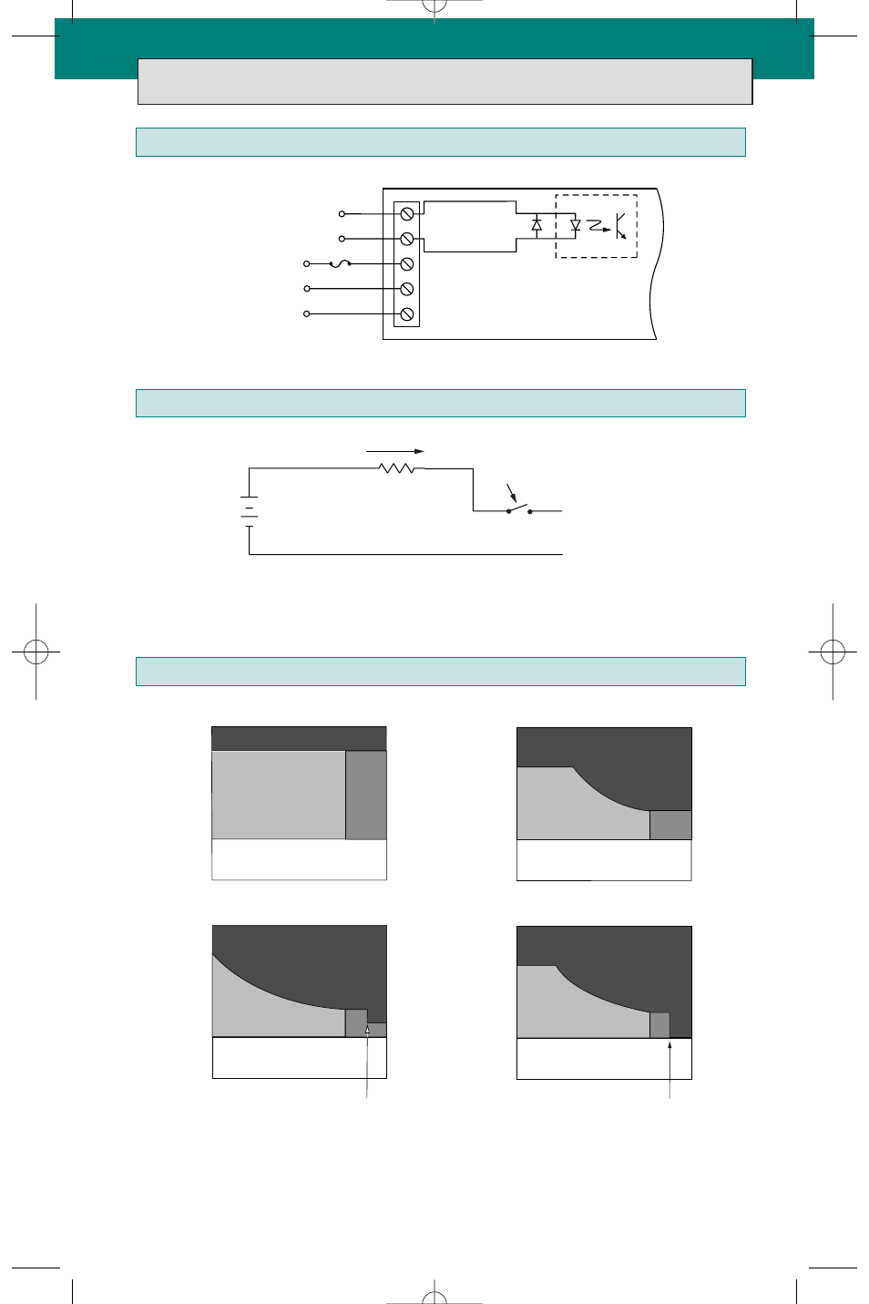
Application Notes
2
The Master Disable input is optically isolated and incorporates a reverse polarity
protection diode. Apply a current of up to 20 mA to disable output(s). See ComPAC
data sheet for minimum levels.
Master Disable Drive Circuit
Input Connections
Input Operating Voltage
Disable +
Disable –
V
IN
+
V
IN
–
GND
Master Disable
DC Input
Earth Ground
Long Term Safe Operating Curves. I.S.W. = Input Surge Withstand (no
disruption of performance, 1% duty cycle max.).
R.E. = Ratings Exceeded. S.D. = Shutdown. For short duration transient
capability, refer to product specifications.
20 mA Max.
Disable
DIS+
DIS–
+
V
0.1 1 10ms 100 1000
100V
Normal Operating Area
I.S.W.
Full Load
100V
Standard
Wide Range
24V Inputs
0.1 1 10ms 100 1000
800V
Normal Operating Area
I.S.W.
Full Load
300V Input
S.D.
160V
0.1 1 10ms 100 1000
Normal Operating Area
I.S.W.
Full Load
48V Input
R.E.
276V
Normal Operating Area
I.S.W.
Full Load
0.1 1 10ms 100 1000
48V Wide Range Input
R.E.
S.D.
R.E.
R.E.
32V
21V
36V
18V
S.D.
76V
125V
60V
100V
42V
500V
400V
200V
36V
S.D.
S.D.
100V
500ms
500ms
See fuse chart on page 6
- VIPAC Power System 50 – 900 Watt (12 pages)
- Mini MegaPAC AC-DC Switcher (27 pages)
- Autoranging MegaPAC AC-DC Switcher (25 pages)
- Westcor PFC MegaPAC Power Factor Corrected AC-DC Switchers (34 pages)
- 3 Phase MegaPAC AC-DC Switchers (31 pages)
- 3 Phase MegaPAC-EL AC-DC Switchers (30 pages)
- PFC MegaPAC-EL Power Factor Corrected AC-DC Switchers (32 pages)
- Westcor PFC Mini Power Factor Corrected AC-DC Switcher (29 pages)
- FlatPAC Family 50 to 600 Watt AC-DC Switchers F-Series (8 pages)
- FlatPAC Family 50 to 600 Watt AC-DC Switchers U-Series (8 pages)
- VI-200 Family DC-DC Converters and Configurable Power Supplies (99 pages)
- PF175 AC-DC Converter Evaluation Board with External Input Filter (12 pages)
- VI Brick AC Front End Evaluation Board (6 pages)
- VIPAC 28 Vdc MIL-COTS (21 pages)
- VIPAC Array Family of DC-DC Converters Up to 750 Watts (7 pages)
- Maxi Family of DC-DC Converter (89 pages)
- VIPAC Array CONFIGURATION GUIDE (14 pages)
- MegaMod DC-DC Converter Family (8 pages)
- PFC Micro Power Factor Corrected AC-DC Switcher (23 pages)
- PFC MicroS Power Factor Corrected AC-DC Switcher (22 pages)
- Javelin I (15 pages)
- Javelin III (13 pages)
- FlatPAC-EN Compliant Autoranging Switchers (29 pages)
- PRM-AL Customer Evaluation Boards (9 pages)
- VI Chip High Voltage BCM Customer Evaluation Board (4 pages)
- PI31xx-xx-EVAL1 Cool-Power ZVS Isolated DC-DC Converter Evaluation Board (14 pages)
- PI2001-EVAL1 Active ORing Evaluation Board (11 pages)
- PI2002-EVAL1 Active ORing With Load Disconnect Evaluation Board (11 pages)
- PI2003-EVAL1 Active ORing Evaluation Board (8 pages)
- PI2007-EVAL1 48V Bus High Side Active ORing Evaluation Board (10 pages)
- PI2007-EVAL2 12V/15A High Side Active ORing Evaluation Board (9 pages)
- PI2121-EVAL1 Full-Function Active ORing Evaluation Board (12 pages)
- PI2127-EVAL1 60V/12A Full-Function High Side Active ORing Evaluation Board (9 pages)
- PI5101-EVAL1 3.3V/60A High Side Active ORing Evaluation Board (12 pages)
- PI2161-EVAL1 60V/12A High Side High Voltage Load Disconnect Switch Evaluation Board (8 pages)
- DC MegaPAC DC-DC Switcher (18 pages)
- PRM Customer Evaluation Boards (9 pages)
- VI Chip PRM Evaluation Board (27 pages)
- Constant Current (CC) Demonstration Board (17 pages)
- Half-chip PRM-RS Customer Board (19 pages)
- Full-chip PRM-RS Customer Board (19 pages)
- VI Chip Remote Sense PRM Evaluation Board (25 pages)
- VI Chip VTM Evaluation Board (13 pages)
- PI33XX-2X I2C Digital Interface Guide (22 pages)