Utput, Onnection, Ptions – Vicor VIPAC Array CONFIGURATION GUIDE User Manual
Page 7
6
v
i
c
o
r
p
o
w
e
r
.
c
o
m
/
v
c
a
d
O
UTPUT
C
ONNECTION
O
PTIONS
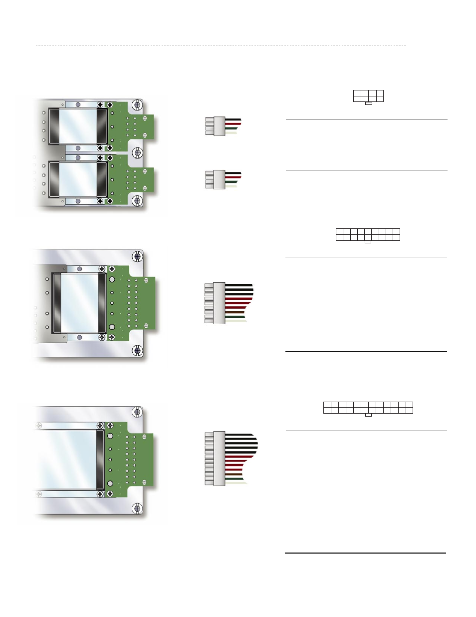
Mating Connector Kits
Vicor P/N 25073
Vicor P/N 25067
Vicor P/N 25061
PlugMate
(Factory Installed Option)
Micro PlugMate
Mini PlugMate
Maxi PlugMate
Pin #
Function
Pin #
Function
1
+Vout
5
+Vout
2
+Vout
6 N/C
3
–Vout
7
SC
4
–Vout
8
–Vout
Pin #
Function
Pin #
Function
1
+Vout
10
+Vout
2
+Vout
11
+Vout
3
+Vout
12
+Vout
4
N/C
13
+S
5
N/C
14
SC
6
N/C
15
–S
7
–Vout
16
–Vout
8
–Vout
17
–Vout
9
–Vout
18
–Vout
Pin #
Function
Pin #
Function
1
+Vout
13
+Vout
2
+Vout
14
+Vout
3
+Vout
15
+Vout
4
+Vout
16
+Vout
5
+Vout
17
+Vout
6
N/C
18
+S
7
SC
19
–S
8
–Vout
20
–Vout
9
–Vout
21
–Vout
10
–Vout
22
–Vout
11
–Vout
23
–Vout
12
–Vout
24
–Vout
1
4
5
8
1
9
10
18
1
12
13
24
Mating Connector
Amp. P/N Vicor P/N
Housing TYC-794657-8
25056
Pin 1-106529-2 24796
Kit 25073
Mating Connector
Amp. P/N Vicor P/N
Housing TYC1-794657-8 25050
Pin 1-106529-2 24796
Kit 25067
Mating Connector Amp. P/N Vicor P/N
Housing TYC2-794657-4 25044
Pin 1-106529-2 24796
Kit 25061
Please Note:
VIPACs that contain multiple modules configured as a single output (paralleled for power
or redundancy) MUST have their Outputs and Sense connected to each other at the load.
DO NOT OPERATE A PARALLEL CONFIGURATION WITH ONLY ONE MODULE CONNECTED.
Additionally one module must be designated as “Master” by having all other modules
configured as “Boosters”. Boosters are created by shorting the SC pin to –S.