Input / output connections – Vicor VIPAC Array CONFIGURATION GUIDE User Manual
Page 5
4
v
i
c
o
r
p
o
w
e
r
.
c
o
m
/
v
c
a
d
Pin#
Funct.
1-4
– Vin
5-7
+Vin
8
NC / PR bus
9
PE protective earth
10
Neg. enable
11-13
– Vin
14-17
+Vin
18
NC / PR bus
19
PE protective earth
20
Pos. enable
VA-J and VA-K configurations only
(300 and 375 Vin single Maxi or single Mini)
Pin#
Funct.
1-3
– Vin
4-6
+Vin
7
NC
8
NC / PR bus
9
PE protective earth
10
Neg. enable
11-13
– Vin
14-16
+Vin
17
NC
18
NC / PR bus
19
PE protective earth
20
Pos. enable
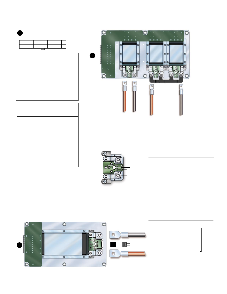
Input / Output Connections
1
11
20
10
Mating Connector
Vicor part #
Amp part#
Housing
24795
2-794657-0
Contacts
24796
1-106529-2
Kit
24828
J1
Input Connector
(View looking into J1)
Solder
Pin #
Pad
Function
1
– Vout
Rd
Trim Down
SC
Secondary Control
Ru
Trim Up
3
+ Vout
Consult design calculator for Rd/Ru trim resis-
tor values located at vicorpower.com
Factory installed Micro LugMate
Ru
SC
Rd
1
3
1
5
*Removable
Jumper
*Removable
Jumper
1
5
J4
1
5
Discrete Output
J1
J1
Factory installed Mini/Maxi LugMate
3
1
3
1
3
1
Shown with the output(s) of two modules
connected in parallel using factory installed
bus bar.**
To disable output(s) apply +5 Vdc between pins
10 and 20 in the polarity indicated
*
P/N 16385
1
5
+S
–S
Parallel Output
Pin # Conn.
Function
Mating Conn.
1
– Vout
J4-1
– Vout
J4-2
– Sense
J4-3
Secondary Control
P/N
16385
J4-4
+ Sense
J4-5
+ Vout
5
+ Vout
*Removable jumpers in J4 are factory installed for local
sensing. For remote sensing the +Sense pins should be
tied to the same point on the +Out power bus;
the -Sense pins should be tied to the same point the -
Out power bus.