Parallel, Redundant connections – Vicor VIPAC Array CONFIGURATION GUIDE User Manual
Page 6
v
i
c
o
r
p
o
w
e
r
.
c
o
m
/
v
c
a
d
5
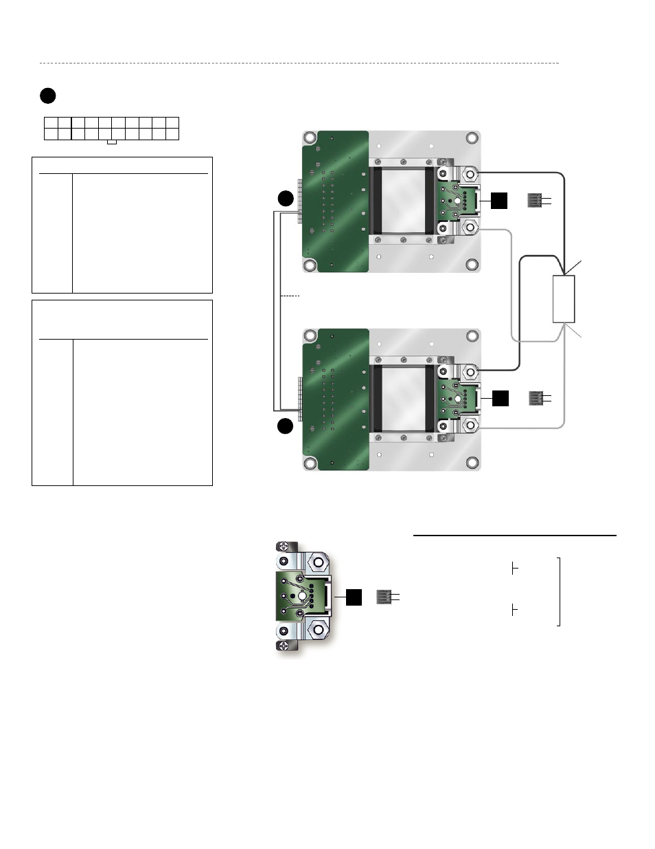
Parallel
***
/ Redundant Connections
*
J1
J1
L
O
A
D
PR bus leads should be connected to like pin#’s
on redundant arrays when equipped with optional
current share transformer. Twist wires and daisy
chain rather than a star connect. Keep length as
short as possible.***
Pin # Conn.
Function
Mating Conn.
1
– Vout
J4-1
– Vout
J4-2
– Sense
J4-3
Secondary Control
P/N 16385
J4-4
+ Sense
J4-5
+ Vout
5
+ Vout
*Removable
Jumper
* Removable
Jumper
Factory installed Mini/Maxi LugMate
*
P/N 16385
J4
+S
–S
–S
+S
1
5
1
5
1
5
*
P/N 16385
J4
1
5
Mating Connector
Vicor part #
Amp part#
Housing
24795
2-794657-0
Contacts
24796
1-106529-2
Kit
24828
J1
Input Connector
(View looking into J1)
J4
+S
–S
*
P/N 16385
1
5
+S
–S
1
11
20
10
Pin#
Funct.
1-4
– Vin
5-7
+Vin
8
NC / PR bus
9
PE protective earth
10
Neg. enable
11-13
– Vin
14-17
+Vin
18
NC / PR bus
19
PE protective earth
20
Pos. enable
VA-J and VA-K configurations only
(300 and 375 Vin single Maxi or single Mini)
Pin#
Funct.
1-3
– Vin
4-6
+Vin
7
NC
8
NC / PR bus
9
PE protective earth
10
Neg. enable
11-13
– Vin
14-16
+Vin
17
NC
18
NC / PR bus
19
PE protective earth
20
Pos. enable
To disable output(s) apply +5 Vdc between pins
10 and 20 in the polarity indicated
* Removable jumpers in J4 are factory installed for local sensing. For remote sensing and redundant
parallel arrays as illustrated above the +Sense pins should be tied to the same point on the +Out
power
bus; the -Sense pins should be tied to the same point the -Out power bus.
** There should be one master module, this is realized by choosing one module to be the master and
shorting the SC to –S on the other module. Units configured from the factory as paralled will already
have this configured. This should be verified by direct inspection prior to system integration.
*** There should be one master module, this is realized by choosing one module to be the master and
shorting the SC to –S on the other module. This is done by installing a 0
Ω resistor in the space
provided on the lugmate / plugmate.