Ah p, Dimensions, Capacity selection chart – Thermal Transfer Systems Air AHP Series User Manual
Page 2
AH
P
www.thermaltransfer.com
262.554.8330
143
A
IR C
O
O
L
E
D
A
H
P
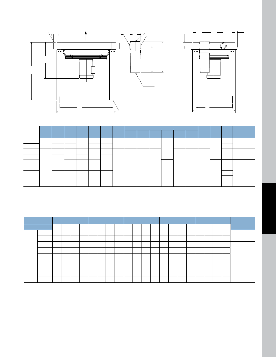
Dimensions
F
C
E
A
B
1.77 TYP
D
AIR
FLOW
K
L
S
P
2" NPT
.62 DIA HOLE
4 PLACES
G
2 PLACES
R
U
V
1.25
TYP
T
M
Optional separator
Recommended
D
G
P
R
s
Optional separator
Model
A
B
C
Approx
E
F
nPT
K
L
M
nPT
nPT
nPT
T
U
V
Model number
AHP-400
22.6
17.96
18.01
13.96
18.68
2.00
4.70
18.60
16.00
.
50
2.00
1.85
4.92
S-600M
AHP-725
34.20
30.56
22.37
18.37
26.56
N/A
6.00
9.34
AHP-950
37.24
26.78
22.76
22.78
33.24
13.76
AHP-1200
41.19
25.07
37.19
3.00
8.00
23.00
20.00
.25
3.00
S-1700M
AHP-1600
34.89 25.95
30.89
2.76
17.86
AHP-2000 36.01
51.04
37.88 27.57
33.88
47.04
20.86
AHP-2500
49.07
43.70 28.01
39.70
45.07
4.009
16.75
30.50
23.25
.50
.75
4.00
8.00 26.68
S-2600M
AHP-3000
51.04
52.52
29.17
48.52
47.04
35.50
AHP-3500
56.30
52.30
39.28
Note: We reserve the right to make reasonable design changes without notice. All Dimensions are in inches.
Capacity selection Chart
max. sCFm @ 5, 10, 15 and 20°F Approach
Recommended
inlet Temp. °F
150
200
250
300
350
Optional
separator
Approach Temp. °F
5
10
15
20
5
10
15
20
5
10
15
20
5
10
15
20
5
10
15
20
Model number
AHP-400 210 384 520 605 175 375 430 500 160 300 400 464 135 250 340 396 125 235 305 355
AHP-725 355 650 890 1025 308 560 760 880 290 545 725 840 245 450 605 701 225 410 540 625
S-600M
AHP-950 480 871 1178 1360 415 754 1020 1180 390 712 950 1100 320 588 785 910 280 520 690 780
AHP-1200 600 1090 1475 1710 520 950 1290 1460 490 900 1200 1380 405 735 980 1130 355 650 865 990
S-1700M
Model
AHP-1600 790 1440 1950 2260 710 1290 1720 1950 660 1200 1600 1860 530 965 1290 1480 460 840 1135 1300
number
AHP-2000 980 1790 2420 2800 870 1580 2140 2460 820 1490 2000 2300 660 1210 1595 1840 572 1040 1400 1610
AHP-2500 1220 2220 3000 3470 1090 1980 2680 3100 1035 1880 2500 2870 784 1426 1980 2270 705 1290 1725 1980
S-2600M
AHP-3000 1450 2650 3580 4120 1295 2360 3200 3710 1243 2260 3000 3450 985 1794 2360 2715 840 1530 2040 2350
AHP-3500 1680 3064 4140 4800 1530 2785 3760 4320 1460 2660 3500 4015 1150 2090 2760 3200 950 1740 2350 2700
Above specifications are based on 80 to 125 PSIG operating pressures. Maximum pressure drop, less than 3 psi. A flexible metal hose must be properly installed between the
compressor and aftercooler to validate warranty. In addition, for mobile and other applications where there may be additional stresses to the connections, our 4-bolt SAE Flange
should be used. Consult factory for pricing and availability.