Dimensions, Selection procedure, Four pass – Thermal Transfer Systems EC Series User Manual
Page 3: Oil temperature
EC
262.554.8330
www.thermaltransfer.com
86
W
A
T
E
R C
O
O
L
E
D
EC
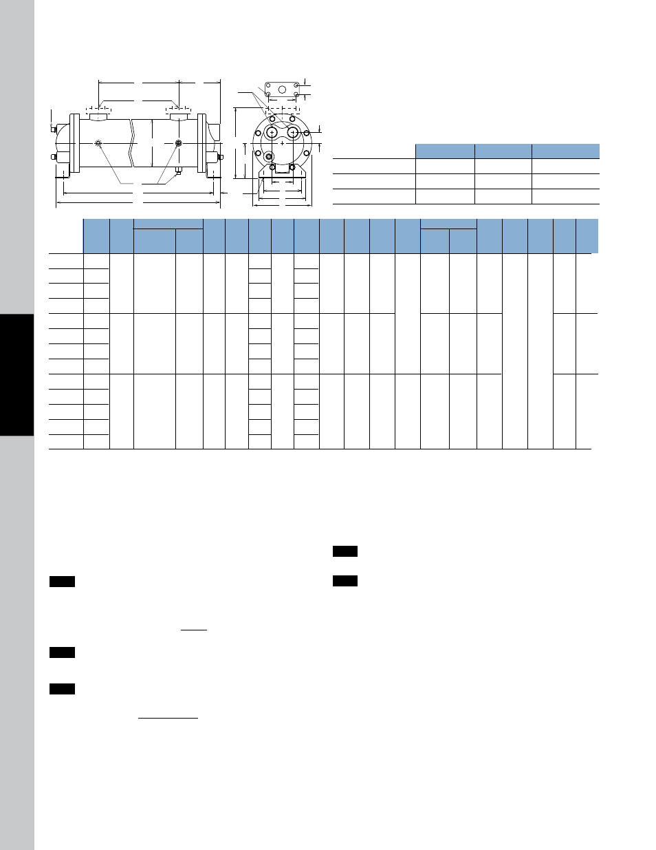
Dimensions
SAe Flange Size
X
Y
Z
1-1/2
1.41
2.75
1/2 - 13
2
1.69
3.06
UNC-2B
3
2.44
4.19
5/8 - 11 UNC 2B
F
G
N
E
H
M
T
K
L
B
C
P
D
U
J
A
Z (4 places)
Y
X
R
S
NOTE: We reserve the right to make reasonable design changes without notice. All dimensions are in inches.
MODEL
A
B
NPT
BSPP
SAE O-RING
SAE
FLANGE
NPT
BSPP
FLANGE
SAE
O-RING
NPT
BSPP
C
D
E
F
G
H
J
K
L
M
U
T
N
P
NPT
BSPP
R
NPT
BSPP
S
EC-1014
EC-1024
EC-1036
EC-1054
EC-1224
EC-1236
EC-1254
EC-1272
EC-1724
EC-1736
EC-1754
EC-1772
EC-1784
19.87
29.87
41.87
59.87
29.78
41.78
59.78
77.78
31.61
43.61
61.61
79.61
91.61
10.12
20.12
32.12
50.12
18.97
30.97
48.97
66.97
18.75
30.75
48.75
66.75
78.75
18.38
28.38
40.38
58.38
27.84
39.84
57.84
75.84
29.25
41.25
59.25
77.25
89.25
6.75
DIA.
7.75
DIA.
10.50
DIA.
5.25
DIA.
6.25
DIA.
8.50
DIA.
7.75
8.75
11.50
8.00
9.38
12.50
4.00
4.50
5.75
4.82
5.44
7.06
.75
1.00
1.81
4.00
5.00
7.00
5.25
6.25
8.25
.50
x
.75
SLOT
.62
x
.88
SLOT
1
1
/
2
2
3
#24
SAE
#32
SAE
N/A
1
1
1
/
2
2
(3)
3/8
(3)
3/8
2.40
2.82
4.25
1.20
1.41
1.41
Four Pass
NOTE: We reserve the right to make reasonable design changes without notice. All dimensions are in inches.
Selection Procedure
Performance Curves are based on 100SSU oil leaving the cooler 40°F
higher than the incoming water temperature (40°F approach temperature).
Step 1
Determine the Heat load. This will vary with different systems,
but typically coolers are sized to remove 25 to 50% of the input
nameplate horsepower. (Example: 100 HP Power Unit x .33 = 33
HP Heat load.)
If BTU/Hr. is known: HP = BTU/Hr
2545
Step 2
Determine Approach Temperature.
Desired oil leaving cooler °F – Water Inlet temp. °F = Actual
Approach
Step 3
Determine Curve Horsepower Heat load. Enter the
information from above:
HP heat load x 40 x Viscosity = Curve
Actual Approach Correction A Horsepower
Step 4
enter curves at oil flow through cooler and curve horsepower.
Any curve above the intersecting point will work.
Step 5
Determine Oil Pressure Drop from Curves. Multiply pressure
drop from curve by correction factor B found on oil viscosity
correction curve.
l
= 5 PSI; n = 10 PSI; s = 20 PSI.
Oil Temperature
Oil coolers can be selected by using entering or leaving oil tempertures.
Typical operating temperature ranges are:
Hydraulic Motor Oil
110°F - 130°F
Hydrostatic Drive Oil
130°F - 180°F
Lube Oil Circuits
110°F - 130°F
Automatic Transmission Fluid
200°F - 300°F