Installation, Aeration adjustment, Wiring diagram – Regency Bellavista B36XTCE Medium Gas Fireplace User Manual
Page 56: Proflame system wiring diagram
56
Regency B36XTCE Gas Fireplace
INSTALLATION
AERATION ADJUSTMENT
The burner aeration is factory set but may need
adjusting due to either the local gas supply or
altitude. Open the air shutter for a blue fl ame or
close for a more yellow fl ame.
Minimum Air Shutter Opening:
NG 1/4"
LP 3/8"
CAUTION: Carbon will be produced if air shutter
is tightly closed.
Note: Any damage due to carboning
resulting from improperly setting
the aeration controls is NOT covered
under warranty.
Air shutter rod - located to the left
of the valve assembly.
WIRING DIAGRAM
CAUTION: Label all wires prior to disconnection
when servicing controls. Wiring errors can cause
improper and dangerous operation.
Caution: Ensure that the wires do not touch any
hot surfaces and are away from sharp edges.
This heater does not require a 120V A.C. supply for operation. In case of a power failure, the burner switch and the optional remote control/thermostat will
continue to operate. However, a 120V A.C. power supply is needed for the fan/blower operation.
(Do not cut the ground terminal off under any circumstances.)
NOTE: Even if the fan is not purchased with the unit, it is still a good idea to bring power to the receptacle box (provided with the unit) in case
the fan is installed at a later date.
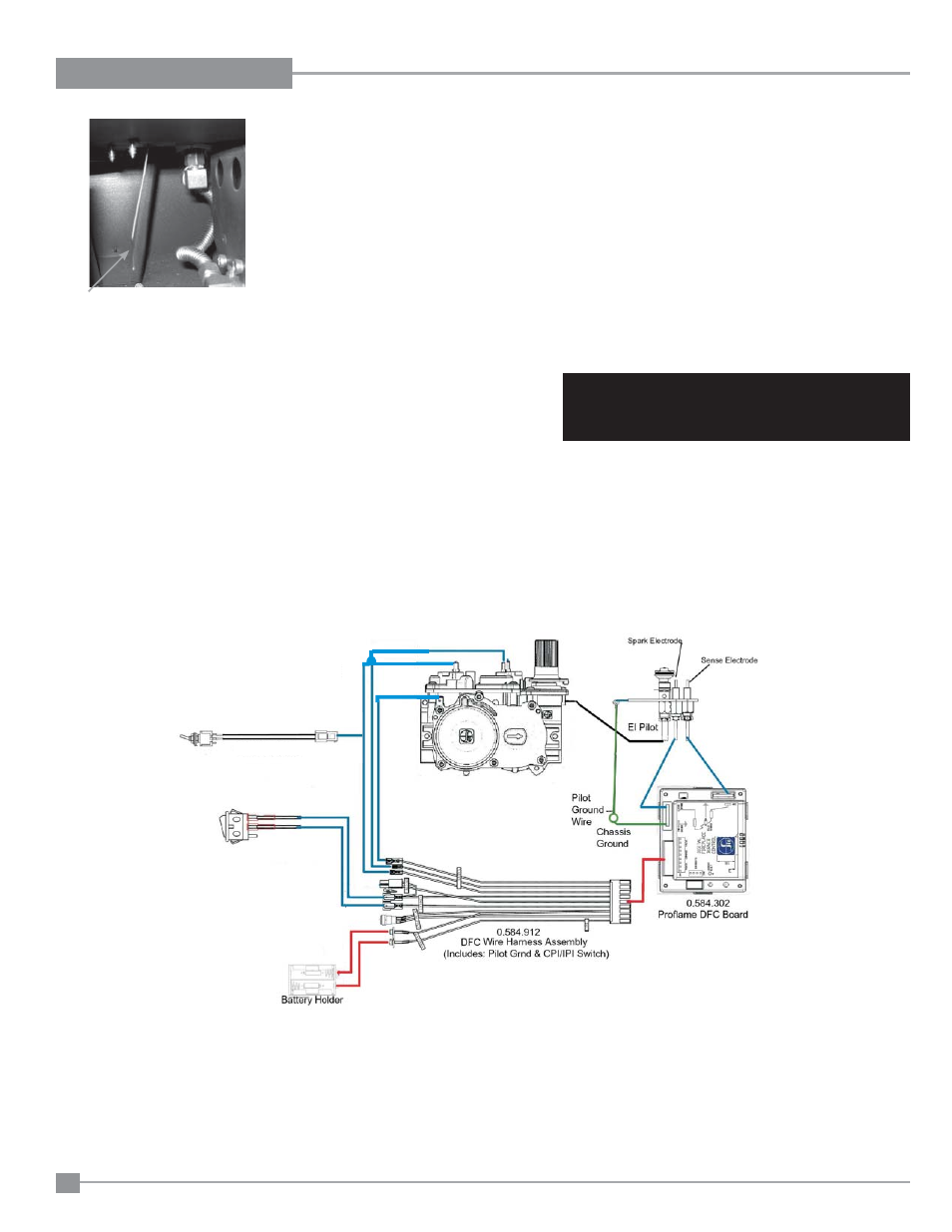
PROFLAME SYSTEM WIRING DIAGRAM
CONFIGURATION: 886 ON/OFF STAND ALONE
0.886.001
Proflame Valve
Standard Main On/Off Switch
or Optional Wall Switch
Note: 4 AA batteries must be installed to operate
the burner switch.
Do not use a 9 volt battery.
SureFire™ Switch
IMPORTANT:
If the optional remote control is used, the AA batteries normally installed into the battery holder must be removed. The AA batteries in the
receiver now operate the unit. Having AA batteries in both the battery holder and receiver will damage the gas valve.