Schwank STSV User Manual
Page 13
13
STV-JZ I&O Manual
IM090512
RD: MAY 2009
RL: 08A- BA
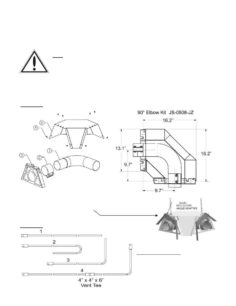
System Configuration
1 Straight line
2 “U” tube with 2 x 90° elbow kits
3 “L” tube with one 90° elbow kit
4 Twinned tubes into common
TEE flue vent
FIGURE 3 SYSTEM ELBOW KIT - see page 49 for 180° elbow dimensions
FIGURE 4 SYSTEM CONFIGURATIONS
90° elbows (JS-0528-JZ) are shipped as a kit with one coupler, one reflector and one plate
hanger. For a 180° elbow, order 2 x 90° kits that connect to create a 180°. An optional kit (JS-
0504-JZ) to angle mount a reflector adjacent to an elbow is also available and must be ordered
separately. The reflectors must be secured to each of the elbow plate hangers, See PAGE 16.
IMPORTANT: Elbow Location / Input: A minimum run of straight radiant tube
must be connected to the burner before any elbow as follows: Input 155 Mbh
(45 kW) = 20 ft (6 m); Inputs 130 Mbh (38 kW) and 110 Mbh (32 Kw) = 15 ft (4.6
m); and Inputs 80 Mbh (23 kW), 60 Mbh (18 kW) a minimum of 10 ft (3 m)
straight tube before elbow.
JS-0504-JZ
Angle mounting of the reflector system either side of an el-
bow requires adapter JS-0504-JZ. The elbow always remains
in a horizontal orientation.