Schwank comfortSchwank - Powder STW-JZ User Manual
Page 24
24
SPW-JZ, STW-JZ(2) / IWP, IW(2) I&O Manual
IM101229
RL: 13A
RD: MAY 2014
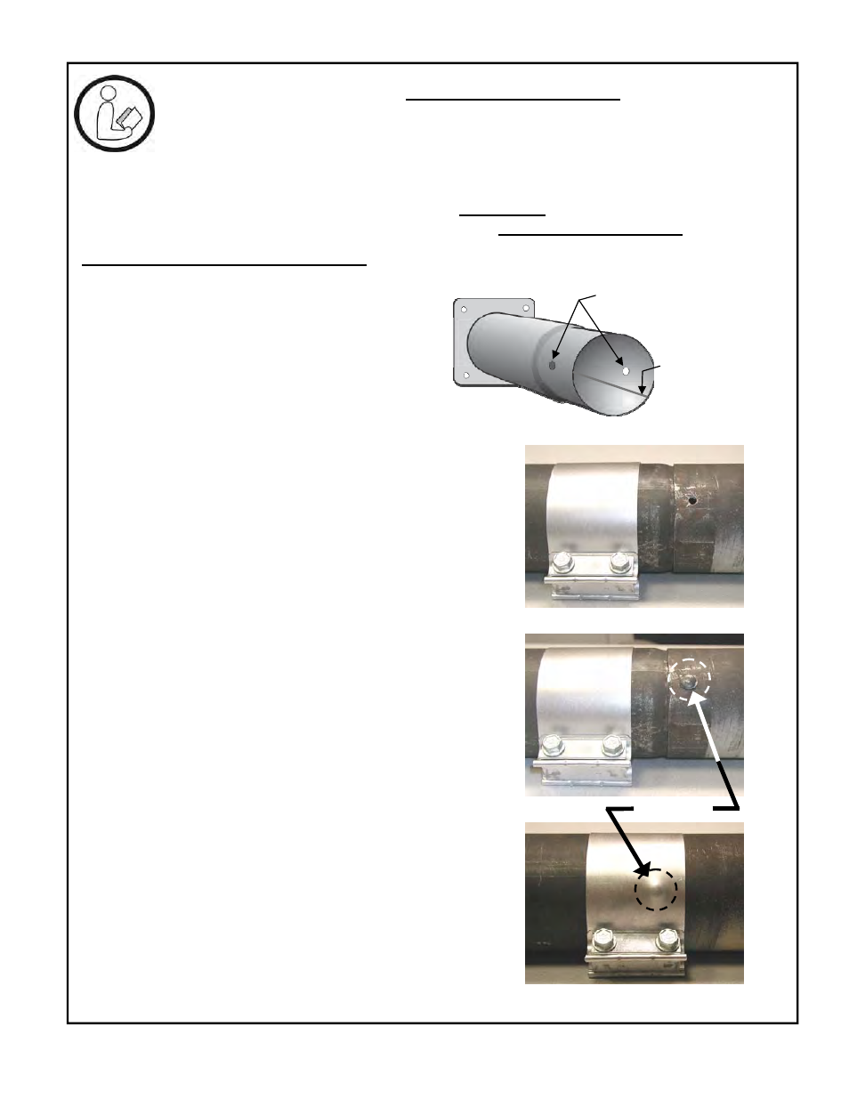
SPECIAL COUPLER INSTALLATION
1. Note the 2 holes opposite each other at
the swaged end of the first tube (flanged)
2. Install the first tube with 2 holes (swaged
end) at the 3 and 9 o’clock position, with
the welded seam located in the lower
half of tube, facing downward
3. Slide the loosened tube coupler on to the
first tube, past the swage
4. The second tube has a ¼” hole at the fe-
male end.
5. Slide second tube over swaged end of
first tube to align the hole in the second
tube with one of the holes in the first tube
6. Final alignment of the holes can be ac-
complished using a screw driver or other
tool
7. IMPORTANT: Insert ¼” rivet into the hole
to secure the tube connection
8. Slide coupler into position – half onto
each tube – covering the rivet head
9. Tighten coupler bolts to 40 ft-lb
10. Install reflectors
9.1 SPECIAL COUPLING: 175,000 & 200,000 Btuh
NOTE
: The joint of 1ST & 2ND tubes of 175,000 & 200,000 heaters experience
strong forces of expansion. Follow instructions below for special coupling of the
tubes.
FIGURE 15 SPECIAL COUPLING:
175,000 & 200,000 Btuh
- Fasten Second Tube to First Tube -
Steps 3
to 6
Step 7
Step 8
1/4” Rivet
Welded seam in
lower half of tube,
facing downward
Holes in swage of 1st
tube: locate at 3 and 9
o’clock