Caution – S&S Cycle Bore Stroker Kit 3 3/16 for Harley-Davidson Sportster Models User Manual
Page 8
●
Crankcase oil scavenging can be greatly improved on 1957 to
1971 engines by converting to 1972 and later style breather
parts combination. If your engine is 1971 or earlier, we
strongly recommend purchase of 1972 and later pump
breather gear, H-D
®
#26331-72 and corresponding gear
retainer lock ring, H-D
®
#11002. These parts are used in place
of early pump breather gear, H-D #26331-60, because slot in
early version is too wide and requires the removal of too
much material from pump body to achieve desired results.
When later parts are used in early pump, scavenger gear,
part H-D #26315-62, must be installed with flat side of gear
facing retainer lock ring.
All reference to Harley-Davidson
®
part numbers is for
identification purposes only. We in no way are implying that any
of S&S
®
Cycle’s products are original equipment parts or that they
are equivalent to the corresponding Harley-Davidson
®
part
number shown.
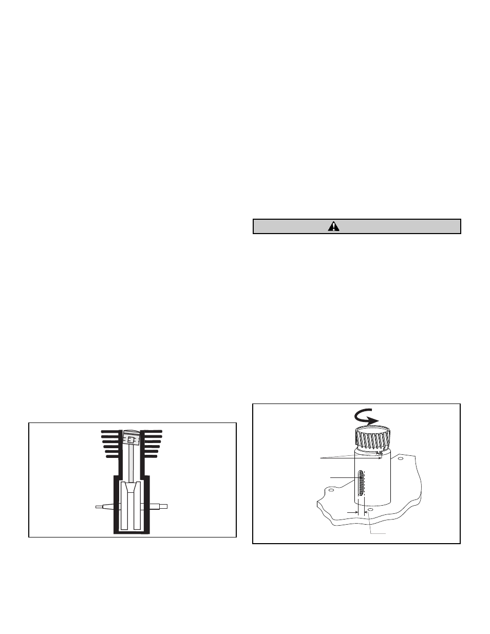
To check and correct crankcase breather timing, perform
following steps:
A.
Before installing oil pump, turn pump gear
counterclockwise until sleeve hole in gear aligns with
slot in pump body. Place .002” shim in opening and
reverse gear until tight. Scribe mark across pump gear
sleeve and pump body at small timing notch on top
edge of body. See Figure 5.
NOTE - Pump gear sleeve is very hard and scribing mark may be
difficult. It may be advantageous to coat top ring of sleeve just
below teeth with Dykem Blue to make marking easier.
B.
Install and time pump in normal manner as in final
assembly.
C.
Install degree wheel on sprocket shaft, and position
pointer at 0° when front piston is at top dead center
(TDC) position.
D.
Rotate front piston to 25° ATC. Be sure oil pump drive
gear is firmly butted against shoulder on pinion shaft.
E.
If scribe mark on pump gear is to left of scribe mark on
body, grind material off engine side of pump drive gear
to allow it to move farther onto shaft until scribe marks
line up. If scribe mark is to right, place shim between
pump drive gear and pinion shaft shoulder to line up
marks. Big twin cam thrust washers, H-D
®
#25550-36,
can be used for this purpose, but are marginal because
they fit pinion shaft poorly. For a better fit we fabricate
our own washers to exact size.
F.
Rotate crankshaft so front piston is at 85° ABC (after
bottom center).
G.
Make a second scribe mark on pump to align with first
scribe mark on body.
H.
Remove pump and carefully grind or file slot wider in
body towards cam cover until it closes at second scribe
mark. Proceed with caution. Do not remove more
material,than absolutely necessary. If unsure, contact
S&S before you make a mistake.
Improper breather timing causes poor oil scavenging from
flywheel cavity and incorrect crankcase air pressure. These
conditions may cause unwarranted engine oil leaks around
gaskets and seals and probable oil burning due to oil blow by
past piston rings. Removal of excessive material from slot
opening is irreversible and damage to body may result.
I.
During final assembly, place oil pump drive gear on
pinion shaft, and time pump in normal fashion. If
material was removed from flywheel side of oil pump
drive gear, it may be necessary to shim between pump
drive gear and pinion gear.
NOTE - Pinion gear must be flush with or extend out slightly past
splines on pinion shaft so pinion gear end play shim does not
contact pinion shaft splines instead of pinion gear.
8
Figure 4
Scribe mark
Breather gear just
starting to open
Enlarge closing
side only
Figure 5
CAUTION