Caution – S&S Cycle Bore Stroker Kit 3 3/16 for Harley-Davidson Sportster Models User Manual
Page 4
3.
Crankcase and Piston Skirt Clearancing (All)
Connecting Rod Clearance
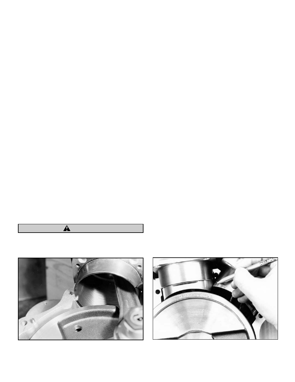
Pictures 2 and 3 show areas to be checked and/or clearanced for
connecting rod to crankcase contact. Procedure to check these
points is performed as follows:
A.
Mock up right side flywheel in crankcase half with
mainshaft and crankpin installed with bearings,
etc. in place.
B.
Assemble pistons without rings on their proper
connecting rods, and place connecting rods on
crankpin. Installation of wristpin button is not necessary.
NOTE - If pistons have piston to piston clearance notches ground
on thrust face edges, place notches toward center of engine.
Consult piston installation instructions included with pistons for
proper piston direction placement.
C.
Install both cylinders and secure each with one nut.
NOTE - If base plates are to be used, be sure they are in place.
D.
Rotate flywheel until rods contact areas to be
clearanced. Note angle that must be filed. See
Picture 4.
E.
Disassemble cylinder and connecting rods and file
crankcase and cylinder spigot for clearance.
NOTE - A minimum of
1
⁄
16
” clearance is required.
F.
Reassemble and check clearance.
G.
This procedure must be done for both crankcase halves.
Insufficient clearance between connecting rods and
crankcases will cause contact and damage to components.
Piston Clearance
Pistons must be clearanced to avoid contact with each other and
with flywheels. See Pictures 5 and 6.
Piston to Piston Clearance
A.
Perform steps A through C in “Connecting Rod
Clearance”.
B.
Rotate flywheel to position where pistons are closest to
each other. See Picture 5.
C.
Check clearance between pistons.
NOTE - A minimum of
1
⁄
16
” clearance is required.
D.
Disassemble cylinders and pistons, and carefully file
edge of piston skirts until clearance is obtained.
Note - Intake valve pocket in piston dome are larger than exhaust
valve pocket. Be sure pistons are installed with larger intake
pockets toward center of engine. Be sure to file material from
skirt on intake side of piston.
E.
Reassemble and check clearance.
Piston to Flywheel Clearance
A.
Perform steps A through C in “Connecting Rod
Clearance”.
B.
Rotate flywheel to position where front piston is closest
to flywheel. See Picture 6.
C.
Check clearance between piston and flywheel.
NOTE - A minimum of
1
⁄
16
” clearance is required.
D.
Disassemble cylinder and piston, and carefully file piston
skirt until clearance is obtained.
E.
Reassemble and check clearance.
F.
Repeat procedure for rear piston.
NOTE - Material removed from pistons for clearancing purposes
will not adversely affect flywheel balance. Some S&S
®
kits utilize
flywheels with diameters smaller than stock (stock flywheels are
7
7
⁄
8
”). This is done to maximize piston skirt length. Our experience
has shown that while it is better to build up flywheel scraper, it
is not absolutely necessary.
4
CAUTION
Picture 4
Picture 5