Caution – S&S Cycle Bore Stroker Kit 3 3/16 for Harley-Davidson Sportster Models User Manual
Page 5
Insufficient clearance between pistons and pistons and
flywheels will cause contact and damage to components.
4.
Connecting Rod Preparation (All)
NOTE - If S&S
®
connecting rods are used, follow instructions
that accompany rods since rod preparation below has already
been done.
If S&S rods are not used, perform following steps:
A.
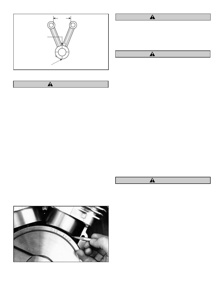
To insure adequate oil on sides of rods and matching
thrust surfaces of flywheels, S&S recommends that four
grooves be ground on each side of both front and rear
connecting rods. See Figure 3. Make these grooves
.020” to .030” deep and .030” to .040” wide and should
be ground 90° from each other. After making grooves,
remove all sharp edges and burrs with emery cloth.
B.
With rods assembled, measure distance between rods
at closest points in wristpin holes. If measurement
exceeds 2.950” as shown in Figure 3, grind female rod
at points where male rod makes contact to achieve
sufficient clearance.
NOTE - Rods clearanced to this dimension provide adequate
clearance for strokes up to and including 5”. Do not remove any
more material than is necessary to obtain required clearance.
Inadequate clearance between rods or too much clearancing
on rods will cause unwarranted stress on connecting rods, rod
bearings, pistons, etc. resulting in possible failure of one or all
aforementioned parts.
C.
Thoroughly clean all parts to remove dirt, filings, etc.
Burrs, dirt, filings, etc. left on connecting rod components
may circulate in oil damaging other parts possibly causing
engine failure.
5.
Lower End Assembly (All)
NOTES
●
S&S flywheels with serial numbers that start with a letter or
those numbered 1670 or higher are made from closed die,
heat treated, steel forgings. They do not have connecting
rod thrust washers like earlier S&S flywheels, because
present flywheel material is harder than thrust washers
previously used.
●
S&S flywheels come with three timing marks. An “F”
stamped by a mark means front cylinder, an “R” means rear
cylinder and a “TF” means top dead center front cylinder.
When front or rear mark is placed in center of timing hole it
means that that cylinder is timed at 40° before top dead
center. We recommend that these stroker engines be timed
at 40° initially. See Step 12, “Ignition Timing”.
●
Usually S&S flywheels are balanced before leaving our
facility. Some customers prefer to do their own balancing or
to have another balancing shop do the work for them. This
is acceptable in most cases. However, we have had some bad
experiences with dynamically balanced flywheels that have
forced us to void our guarantee if flywheels have been
balanced in this fashion.
Flywheels assembled improperly prior to being dynamically
balanced may sustain irreversible damage to mainshaft and
crankpin tapers during actual balancing. S&S voids its
guarantee if flywheels have been balanced in this fashion.
●
Assembling flywheels, mainshafts and connecting rods can
be easy or difficult. Degree of difficulty is determined by
builder technique and parts at his disposal. While S&S
flywheels have been noted for their easy truing qualities,
they can be difficult to true if a defective part is used that
should have been detected before assembly.
●
Cleaning parts prior to and during assembly and keeping
parts clean after final assembly is imperative to minimize
contaminants that may circulate in oil and shorten engine
life. Use cleaning agents that do not leave harmful residues,
and be sure to read and follow manufacturer’s instruction
label before use. Use drills and compressed air to clean all oil
passageways of dirt, filings, etc. whenever possible.
5
Grind four oil
grooves on both
sides of forked rod
Grind stroke
clearance in
this area
2.950
Figure 3
Picture 6
CAUTION
CAUTION
CAUTION
CAUTION