Caution – S&S Cycle Bore Stroker Kit 3 3/16 for Harley-Davidson Sportster Models User Manual
Page 7
I.
Finish assembling flywheels and rods. Following above
procedures will help diagnose problem if difficulty
should arise.
6.
Connecting Rod Alignment (All)
After flywheel assembly is installed in crankcases, rods must
checked for straightness. S&S
®
Rod Checking Pin was
designed to help perform this procedure. It may also be
necessary, to fabricate a rod bending tool.
NOTE - The purpose of this procedure is to correct for machining
tolerance discrepancies in components which may lead to pistons
not running true in cylinder bores. While rods may be straight
and true, it is sometimes necessary, to bend them to correct for
these machining discrepancies. Do not bend rod by using tool in
wristpin hole as this method may distort wristpin bushing. We
also feel that using a piston in lieu of a checking pin may prove
inaccurate due to variations in lengths of piston skirts from one
side of piston to the other.
Pistons which do not run true in cylinder bores may cause
excessive connecting rod side thrusting. This in turn may lead
to premature ring, piston, connecting rod and rod bearing
wear and eventual failure of these parts.
Checking Pin Procedure
A.
Insert checking pin into wristpin hole. Place strips of
paper between checking pin and crankcase cylinder
gasket surface and apply slight downward pressure to
wristpin end of rod by rotating flywheels. Pull papers
out slowly. Drag on papers should be equal.
B.
Rotate flywheels in opposite direction until checking pin
contacts cylinder gasket surface again. Repeat
procedure to rod again. If drag on papers is equal no
bending is required. If one paper is loose, use rod
bending tool to tweak rod in direction of loose paper
and recheck. See Picture 10.
C.
Repeat checking and bending procedure for other rod.
Visual Procedure
A.
Install pistons on rods without rings or wristpin buttons.
Bolt cylinders with gaskets in place.
B.
Move piston tight towards camside of engine.
C.
Turn engine over in normal direction of travel 2 or 3
revolutions and observe piston during process.
D.
Move piston towards driveside of engine and repeat
Step C. If inaccuracies are present due to machining
variations in cases, cylinders or pistons, top land of
piston deck will appear closer to cylinder wall at one
point around circumference. This means that piston is
cocked in cylinder bore and can be corrected by bending
rod in opposite direction. Figure 4 shows an
exaggerated side view of this condition.
E.
Repeat Steps B to D for other cylinder.
NOTE - All engines should be checked upon disassembly for
incorrect piston alignment. This applies to those which are
receiving new pistons as well as those being completely rebuilt.
Observe pistons for wear spots on sides above top compression
ring. If one side near wristpin is worn clean while side opposite
is carboned up, then piston was not running straight and true in
cylinder bore. Piston will also generally show diagonal wear
pattern on thrust faces of skirts and possibly signs of connecting
rod to wristpin boss contact inside piston.
We feel that not enough emphasis is given to checking piston
alignment in cylinder bore. Proper piston alignment means
connecting rods will thrust to sides less minimizing added stress
on pistons, rings, rod bearings and other related parts.
7.
Breather Timing (1957 to 1976)
NOTES
●
Instances of smoking in early models led us to believe that
crankcase breather timing was incorrect. Examination of
several engines has shown that breather timing varies from
engine to engine because of differences in overall width of
crank assembly which changes position of pump drive worm
gear on pinion shaft with respect to pump gear.
When
engine is disassembled, breather timing should be checked.
●
Breather timing should be set so breather valve opens when
front piston is at 20° to 25° after top center (ATC) position,
and closes when front piston is at 85° to 90° after bottom
center (ABC) position.
7
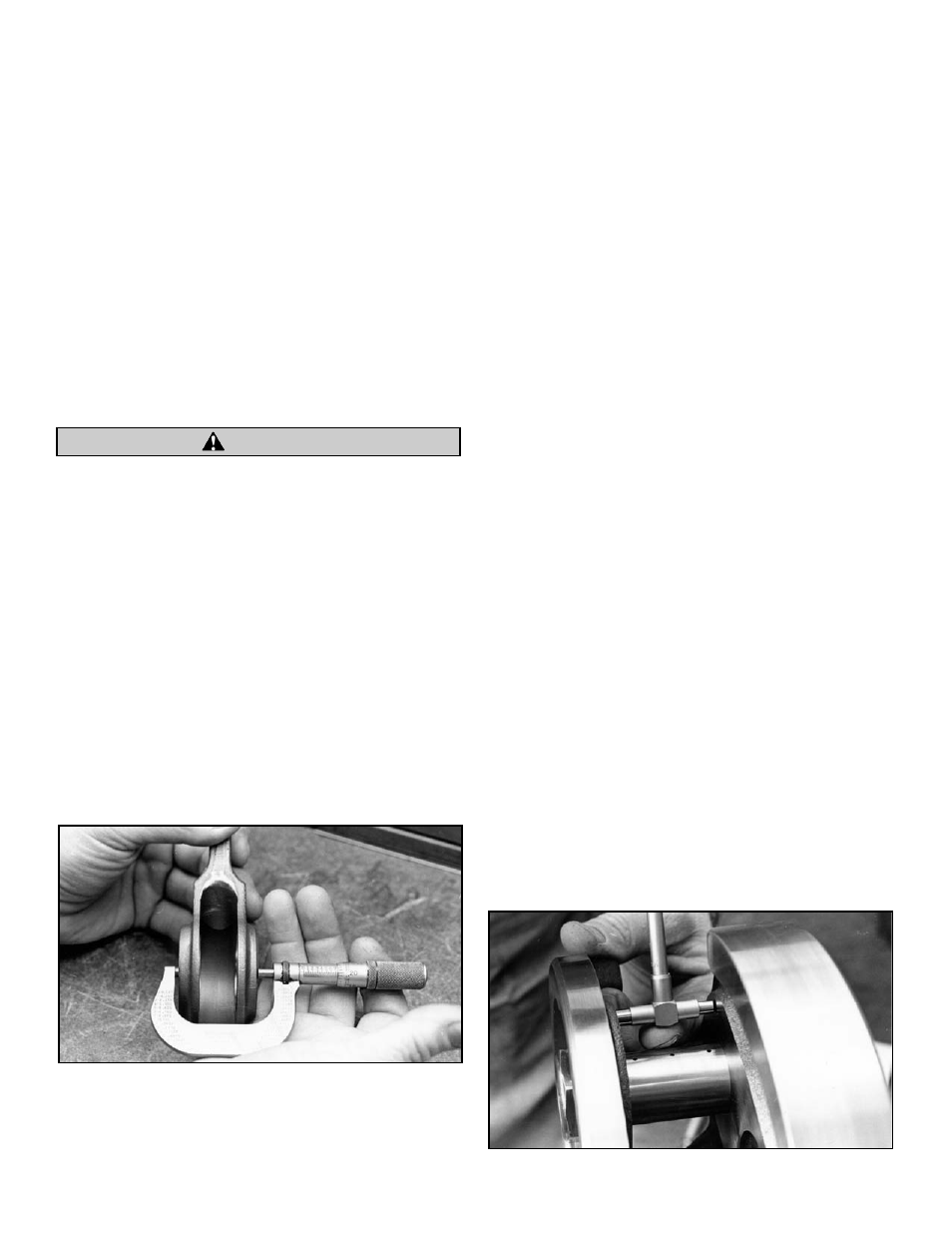
Picture 8
Picture 9
CAUTION