S&S Cycle Standard & Easy Start Gear Drive Camshafts for 2007–up Harley-Davidson Big Twin and 2006 Dyna Models User Manual
Page 6
should be used. Gear sets with less than .0005" of backlash may
whine when run and can cause tooth wear, excessive heat generation
with gear failure, resulting in engine damage. Gear backlash greater
than .002" can cause excessive gear noise or clicking caused by the
reversing of the forces applied by the lifter springs onto the cams, use
the oversized crankshaft gear (PN 33-4160Z) for this situation.
NOTE: Cam drive gears are slightly larger than the stock drive sprockets
and need to be checked for interference with the cam cover before
proceeding.
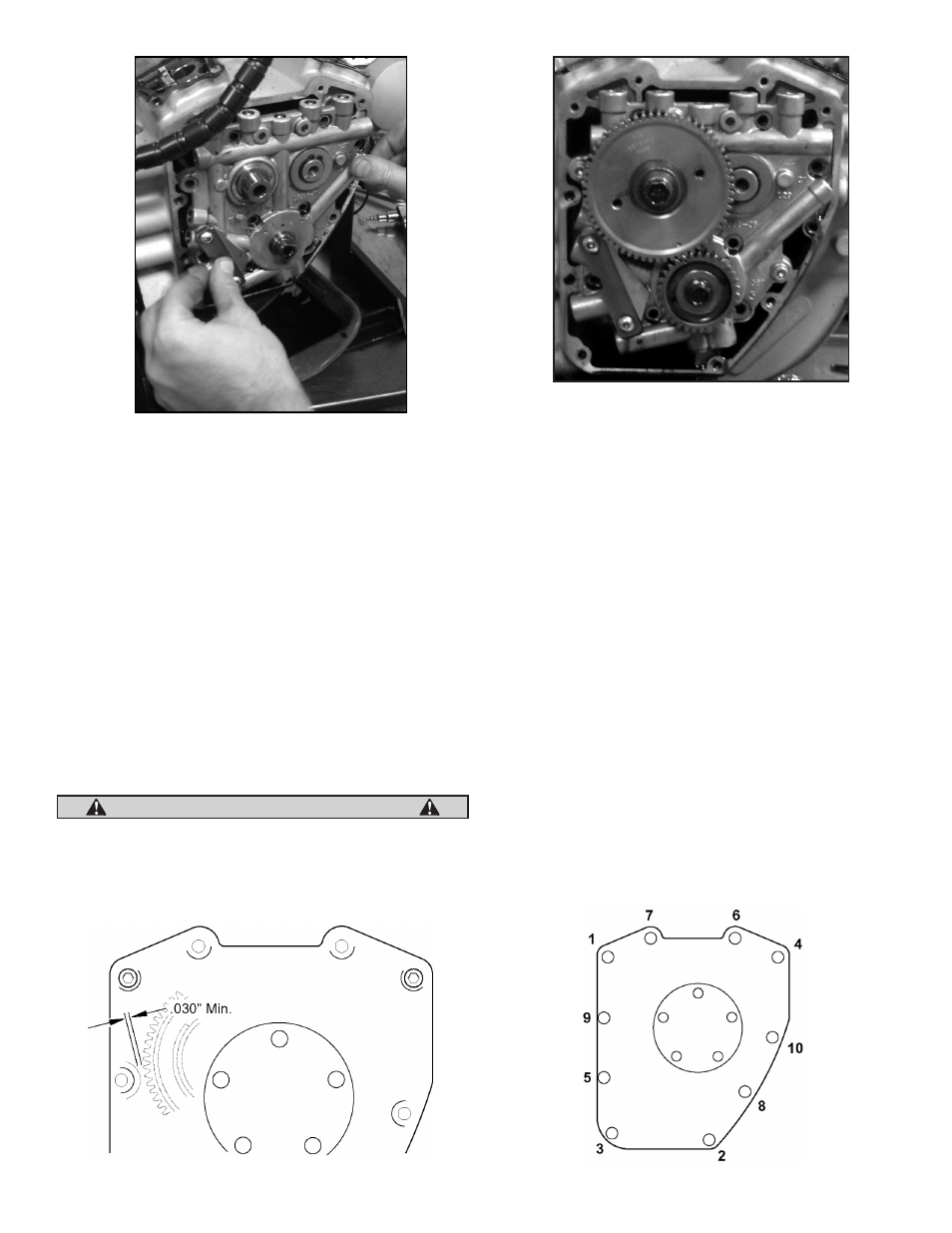
T. Press a small amount of kneadable clay or putty on the cam cover
mounting boss shown. See Figure 1 below. Carefully hold the
cover and cover gasket in the position against the crankcase.
Install mounting bolts (4) near the corners of the cover finger
tight. Push or tap the cam cover towards the engine.
U. Carefully remove the cam cover. Determine the cover to gear
clearance by measuring the impression left in the clay by the
gear at its thinnest point. Clearance should be .030" or more.
If clearance is less than .030", or if the cover contacts the gear,
remove only enough material from the cam cover to obtain the
correct clearance. Repeat Steps T and U if necessary.
Be careful not to grind too deeply and break through to the outside
of the cam cover. Damage to the cam cover caused by removing too
much material is not covered under warranty.
V. Use a new cam cover gasket and install the cam cover. Tighten the
cover bolts 90-120 in-lbs torque in sequence shown. See Figure 2
below.
W. Remove clips to release lifters. If using stock pushrods or S&S®
Quickee pushrods, tappet covers may be left in place, If using S&S
standard adjustable pushrods, tappet covers must be removed.
X. Place transmission in high gear and turn rear wheel to rotate
engine until both lifters for front cylinder are at lowest point in
their travel. The front piston is now at TDC of compression stroke.
If equipped with S&S Easy Start cams, you must use extra care
when adjusting pushrods. Because the decompression lobe
is near TDC, you must make sure that the tappet is not on the
lobe. This will cause incorrect exhaust pushrod adjustment. To
verify correct position, you can rotate the engine in the forward
direction and feel for the exhaust tappet to slightly lift (about
.030") and set back down on base circle. This is the proper point to
adjust the pushrods.
Y. Loosen locknuts on adjustable pushrods and turn adjusters to
make all rods as short as possible.
Z. When installing pushrods, note that longer S&S® pushrods are
for exhaust valves, and shorter ones are for intake. Pass one long
and one short pushrod through assembled pushrod covers. Place
pushrod and cover assemblies through lifter cover. Inner tappet
hole is for intake pushrod, and outer tappet hole is for exhaust
pushrod. If using S&S standard adjustable pushrods, hold a new
6
Picture 10
Picture 11
Figure 1
Figure 2
CAUTION