S&S Cycle Standard & Easy Start Gear Drive Camshafts for 2007–up Harley-Davidson Big Twin and 2006 Dyna Models User Manual
Page 3
Important Notes Regarding Easy Start Camshafts:
• Stock EFI engines require a minimum of 80 PSI cranking
compression, checked with the throttle open, for the ECU to fire the
spark plugs.
• The easy start cams were designed to work with the compression
ratio and displacement combinations that the cam was intended
for. Due to a near infinite number of engine combinations,
manufacturing tolerances, or if the cam is used outside our
recommended compression ratios, occasionally an engine may not
build the required compression to start the bike. For these cases we
offer cams that do not release as much compression. Please call our
technical department at 1-608-627-8324.
• Cranking compression numbers are no longer a valid health check
of the engine. We recommend performing a leak down test.
• S&S recommends that you install new lifters when installing new
cams
• If any service work is performed and the lifters are not replaced, the
lifters must be installed in the original position and orientation.
• If the lifters have been disassembled or bled down for any purpose,
the starter may have difficulty with the initial start. Although the
decompression lobe lifts the lifter body, the lifter is not pumped up
and it will not lift the exhaust valve. You may need to remove the
spark plugs and crank the engine to get oil pressure to the lifters.
• There is no service required with these cams. If you ever have the
cams out for any reason, inspect the mechanism for wear and verify
that the lever operates smoothly.
1- Disassembly
1. Remove pushrods.
a- Remove pushrod cover clips with a small screwdriver and
compress pushrod covers to expose pushrods. Lift rear tire of
motorcycle with a suitable jack. Rotate the engine until one
of the cylinders is on “top dead center compression stroke”
(TDCC). TDCC can be found by rolling the rear tire forward
while watching or feeling the pushrods move through their
travel. When BOTH pushrods are at the lowest point of their
travel and the piston for that cylinder is at TDC, the engine is at
TDCC. Rotate the pushrods to ensure there is no load on them.
If the pushrods will not rotate freely by hand, either the engine
is not on TDCC, or the lifters need to bleed down. It may be
necessary to let the lifters bleed down for a few minutes before
the pushrods will rotate freely.
b- If S&S adjustable pushrods will be used for re-assembly, the
stock pushrods may be cut to remove them at this time. When
cutting pushrods, S&S recommends a bolt cutter be used as it
is the cleanest method. Be sure to only cut the pushrods that
are not loaded and rotate freely by hand.
Cutting the pushrods with a saw may result in metal chips entering
the engine and causing extensive damage which will not be covered
under warranty.
Cutting pushrods without relieving valve spring force on the
pushrods may result in injury.
c- If stock one piece pushrods are to be re-used, remove the gas
tank and rocker box covers. Remove the rocker arm support by
first removing the two smaller bolts which hold the breather
cover in place. Next break loose the four bolts holding the
rocker arm support plate in place with an alternating pattern.
Remove the four rocker arm support plate bolts, and then
the rocker arm support assembly. The pushrods may now
be removed by sliding them up into the head slightly and
then pulling the bottom of the pushrod towards you. Mark
the original pushrod location as it is removed to ensure it is
replaced in its original position. The intake pushrod is shorter
than the exhaust pushrod. Interchanging the intake and
exhaust pushrods upon reassembly, will cause the intake valve
to stay open on the compression stroke and the engine will not
run.
d- Rotate the engine so the other cylinder is on TDC compression
and repeat the above procedure.
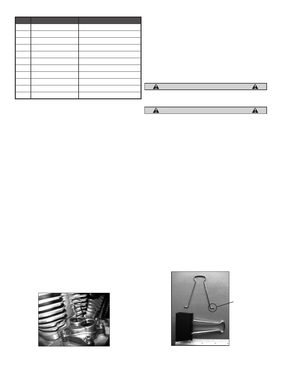
2. Remove cam cover and gasket. Secure lifters with a magnetic lifter
tool or a tool made from a large binder clip spring. See Pictures 2
and 3 below.
3. Rotate rear wheel to align timing marks on the primary cam chain.
4. Remove the primary chain tensioner by removing the two
retaining bolts and install sprocket locking tool.
5. Remove the crank sprocket bolt and flat washer.
6. Remove rear cam sprocket bolt and flat washer.
7. Remove sprocket locking tool.
8. Gently pry off crank sprocket and rear cam sprocket.
3
Cam
Intended Displacement
Intended Compression Ratio
551
88–106
9.0–10.0
557
96-103
9.6-10.0
570
88–106
9.0–10.0
583
88–106
9.0–10.0
585
88–106
9.2–10.5
625
95+
10.0–10.75
635
106-124
10.2-10.8
640
95+
10.5–11.5
675
120+
11+
HP103
103
9.6-10.0
MR103
103
9.6-10.0
CAUTION
WARNING
Picture 2
Grind points
on each end
Picture 3