S&S Cycle Standard & Easy Start Gear Drive Camshafts for 2007–up Harley-Davidson Big Twin and 2006 Dyna Models User Manual
Page 4
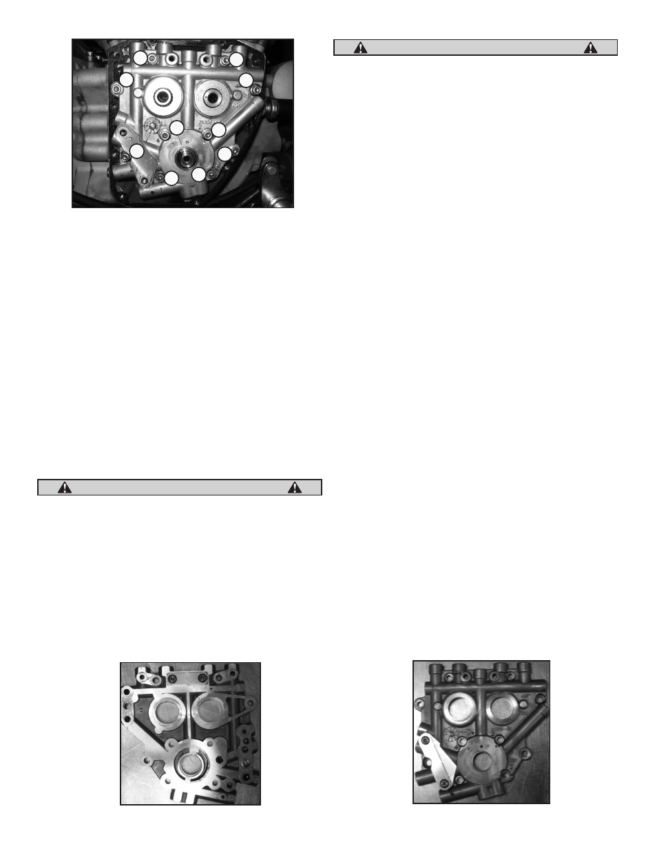
Cam Support Plate and Cam Removal
1. Gradually loosen and remove the four oil pump bolts/washers
according to the sequence shown in Picture 4, next page.
2. Gradually loosen and remove the six support plate bolts/washers
according to the sequence shown in Picture 4, next page.
3. Remove spacer from rear cam, this spacer is thicker than the front
spacer.
4. Remove cam plate and cams from engine.
5. Remove retaining ring and spacer from front cam. This spacer is
0.100" thick.
6. Remove the secondary cam chain tensioner.
7. Remove the cams and cam chain.
8. Check pinion shaft runout. Place an indicator on the end of pinion
shaft at camsupport plate bushing surface and rotate engine;
reading must be .003" or less total indicated runout (TIR). If
reading is greater than .003" TIR the crankshaft must be repaired
or replaced to correctexcess runout before installing gear drive
cams.
If pinion shaft has more than .003" total indicated runout (TIR), the
crankshaft must be repaired or replaced to correct excess runout
before installing gear drive cams. Failure to correct excess runout
may lead to engine damage not covered under S&S warranty.
2- Installing the Cam Gear Drive
A. Install new needle bearings provided with the S&S® Camshaft
installation kit 106-6068 or with bearings from another source.
Cam bearings must be Torrington B-168 full complement bearing
or equivalent.
Using existing needle bearings may cause engine or cam damage
due to increased tolerances from wear and higher loading of cams.
Always replace cam bearings with the ones provided in this kit or
another source.
B. Install the new hydraulic block off plates where the front and rear
chain tensioners were located, tighten fasteners to 100-120 in lbs.
See Picture 5 & 6 below.
C. When using 551G, 570G, 583G, 585G, 625G, or 640G camshafts
clearance between the pinion bearing boss and the rear cam lobe
must be checked. See Pictures 7 & 8, top of next page. Remove
just enough material to provide .030" of clearance between
the top of the cam lobe and the pinion bearing boss when the
camshafts are rotated in the inner needle bearing. Also check
clearances between the cam lobe and the tappet guide bosses.
To avoid contamination of the engine with chips, we recommend
that all holes in the gear case be taped off with duct tape and that
the gear case be thoroughly cleaned with parts cleaner or solvent
after clearancing is performed.
D. Apply assembly lube to the bearing bore of the support plate
and the outer races of the cam and the decompression lever, if
equipped. Slide the S&S® front cam into place.
E. Install the .110" washer on the other side of the support plate over
the front cam.
F. Install a new loaded retaining ring onto the end of the front cam
to secure it in place.
NOTE: Before reinstalling cam support plate, replace oil pump o-ring
(supplied in kit) even if the original appears to be in good condition. The
stock o-ring may have become brittle and provide a poor seal if reused.
G. Apply a thin layer of assembly lube to the rear cam journal, lobe
surfaces, inner bearing surfaces and decompression lever, if
equipped.
H. Slide the rear cam into place aligning the two timing marks on the
back of the cam gears. See Picture 9a, bottom, next page.
I. Align the camshafts with the needle bearings in the case and
carefully side the support plate over the crankcase dowels. See
Picture 10, page 6.
NOTE: The support plate assembly should slide into place without
resistance. If resistance is encountered, determine the cause and correct the
problem before proceeding. Do not force the support plate into position.
The camshafts must be installed into the cam support plate before
installation. Failure to due so could result in damage to the cam support
plate and bearing surface.
J. Recheck the cam timing by visually inspecting the timing marks
on the front of the camshafts. See Picture 9, bottom, next page.
4
Picture 4
1
1
3
4
2
4
2
6
3
5
CAUTION
CAUTION
Picture 5
Picture 6