S&S Cycle Standard & Easy Start Gear Drive Camshafts for 2007–up Harley-Davidson Big Twin and 2006 Dyna Models User Manual
Page 5
Support plate screws that pass through alignment dowels can be
easily stripped (See Picture 4, page 4) when applying maximum
120 in-lbs torque as recommended by Harley-Davidson®.
K. Loosely install the support plate screws with a drop of threadlock
242 or 243 (blue). Alternately tighten the screws to 95 in-lbs.
torque following the sequence shown. See Picture 4, above.
L. Install the oil pump screws into locations in Picture 4, above,
with a drop of threadlock 242 or 243 (blue). Screw them into the oil
pump until they bottom out and then back them off ¼ turn. Rotate
the crankshaft allowing the pump to find its center and alternately
tighten the screws in order to 45 in-lbs. Torque the screws to 95 in-
lbs and then rotate the crankshaft again checking for any binding
in the oil pump gears.
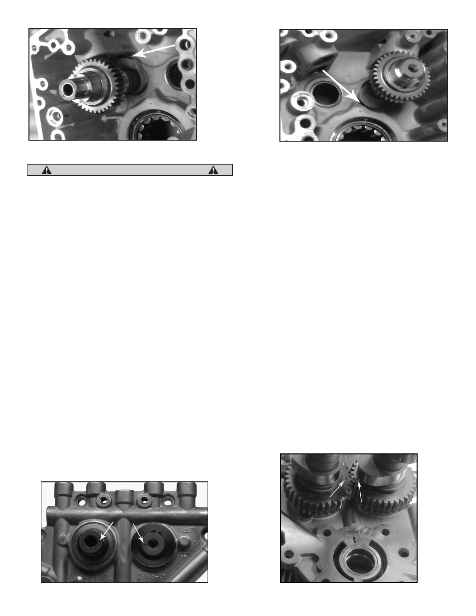
M. Check the inner camshaft gears for proper backlash. Due to the
manufacturing tolerances of the cam support plate camshaft
alignment may cause the inner gears to bind or become too
loose. Check the rear cam for endplay by moving the camshaft in
and out of the cam support plate while rotating the cam in several
positions 360°. There should be no binding in any position when
rotated. If binding does occur replace the rear inner cam gear
with a undersized inner gear (PN 33-4277). Too much backlash
between gears can cause excessive wear and valve train noise use
the oversized inner gear (PN 33-4278) to decrease backlash. Over
and undersized inner gears are not supplied with this kit.
NOTE: Crankshaft and Outer cam drive gears have a light press fit on
their respective shafts. Start gears squarely on their shafts and use their
mounting bolts to pull them all the way into position.
N. Place the crankshaft gear on the crankshaft with the timing mark
outward. Apply a drop of red threadlock 262, 271, or 272 to threads of
5/16-18 x ¾" Grade 8 crankshaft gear bolt provided in kit (PN 33-5240)
or obtain one from another source. Apply a drop of clean 20W-50
engine oil under the bolt flange. Using the washer removed in
disassembly, install the crankshaft gear bolt and tighten to 25 ft-lbs
torque.
O. If necessary place the transmission in high gear and turn the
rear wheel to rotate the engine until the timing mark on the
crankshaft pinion gear is able to be aligned with the outer cam
gear timing mark.
P. Place the .188 x 150 x .57 key into the rear cam shaft keyway.
Position the outer drive gear on the rear camshaft with the timing
mark facing outward. Rotate the drive gear and camshafts until
the drive gear and crankshaft gear timing marks are aligned. See
Picture 11
next page.
Q. Ensure that the gear is properly aligned with the timing mark on
the crank gear and the key on the rear camshaft. Start the outer
drive gear by hand and use the screw and washer, 50-0132 and 50-
7056, provided in the installation kit to drive the outer gear onto
the rear camshaft.
R. Apply a drop of red threadlock 262, 272, or 271 to the threads of
the 3/8"-24 x 1.75" Grade 8 cam drive gear screw. Apply a drop of
clean 20W-50 engine oil under the bolt flange. Using the thick
washer provided, install the cam drive gear bolt and tighten to 34
ft-lbs torque.
NOTE: The axial thrust of the rear cam is controlled by the inner gear collar
and the outer gear collar. Check the outer gear to make sure that it is fully
seated against the rear cam shoulder. Failure to fully seat the outer gear
will cause needle bearing and cam support plate damage.
S. To check backlash in the outer drive gear set, rotate the 62 teeth cam
drive gear back and forth while keeping the pinion gear locked in
one place with the engine. The minimal required backlash for the
gear set should be between .0005" and .001" and no more than .002"
for cold gears. Both gear sets should roll freely with no radial or axial
binding. When checking backlash the gear mesh shows less than
.0005" of backlash then a smaller crankshaft gear size (PN33-4160X)
5
CAUTION
Picture 7
Picture 8
Picture 9
Picture 9a