S&S Cycle 2006-Up Gear Drive Cams for Harley-Davidson Twin Cam 88 Engines User Manual
Page 8
8
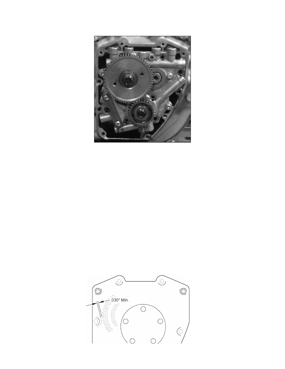
P- Place the .188 x 150 x .57 key into the rear cam shaft keyway. Position the outer dive gear on the rear camshaft with the timing mark facing
outward. Rotate the drive gear and camshafts until the drive gear and crankshaft gear timing marks are aligned. See Picture 11.
Picture 11
Q- Ensure that the gear is properly aligned with the timing mark on the crank gear and the key on the rear camshaft. Start the outer drive
gear by hand and use the screw and washer, 50-0132 and 50-7056, provided in the installation kit to drive the outer gear onto the rear
camshaft.
R- Apply a drop of red threadlock 262, 272 or 271 to the threads of the 3/8”-24 x 1.75” Grade 8 cam drive gear screw. Apply a drop of clean 20W-
50 engine oil under the bolt flange. Using the thick washer provided, install the cam drive gear bolt and tighten to 34 ft-lbs torque.
NOTE: The axial thrust of the rear cam is controlled by the inner gear collar and the outer gear collar. Check the outer gear to make sure that it is fully
seated against the rear cam shoulder. Failure to fully seat the outer gear will cause needle bearing and cam support plate damage.
S- To check backlash in the outer drive gear set, rotate the 62 teeth cam drive gear back and forth while keeping the pinion gear locked in
one place with the engine. The minimal required backlash for the gear set should be between .0005” and .001” and no more than .002” for
cold gears. Both gear sets should roll freely with no radial or axial binding. When checking backlash the gear mesh shows less than .0005”
of backlash then a smaller crankshaft gear size ( PN 33-4160X) should be used. Gear sets with less than .0005” of backlash may whine when
run and can cause tooth wear, excessive heat generation with gear failure, resulting in engine damage. Gear backlash greater than .002” can
cause excessive gear noise or clicking caused by the reversing of the forces applied by the lifter springs onto the cams, use the oversized
crankshaft gear (PN 33-4160Z) for this situation.
NOTE: Cam drive gears are slightly larger than the stock drive sprockets and need to be checked for interference with the cam cover before proceeding.
T- Press a small amount of kneadable clay or putty on the cam cover mounting boss shown. See Figure 3. Carefully hold the cover and cover
gasket in the position against the crankcase. Install mounting bolts (4) near the corners of the cover finger tight. Push or tap the cam cover
towards the engine.
Figure 3