S&S Cycle 2006-Up Gear Drive Cams for Harley-Davidson Twin Cam 88 Engines User Manual
Page 7
7
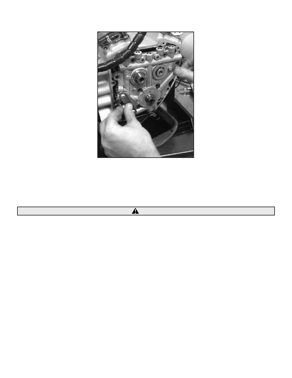
I- Align the camshafts with the needle bearings in the case and carefully side the support plate over the crankcase dowels. See Picture 10.
Picture 10
NOTE: The support plate assembly should slide into place without resistance. If resistance is encountered, determine the cause and correct the problem
before proceeding. Do not force the support plate into position. The camshafts must be installed into the cam support plate before installation. Failure to
due so could result in damage to the cam support plate and bearing surface.
J- Recheck the cam timing by visually inspecting the timing marks on the front of the camshafts. See Picture 9.
CAUTION
Support plate screws that pass through alignment dowels can be easily stripped (See positions 1 & 2, in Figure 2) when applying maximum
120 in-lbs torque as recommended by Harley-Davidson®.
K- Loosely install the support plate screws with a drop of threadlock 242 or 243 (blue). Alternately tighten the screws to 95 in-lbs. torque
following the sequence shown. See Figure 2.
L- Install the oil pump screws into locations in Figure 1 with a drop of threadlock 242 or 243 (blue). Screw them into the oil pump until they
bottom out and then back them off ¼ turn. Rotate the crankshaft allowing the pump to find its center and alternately tighten the screws in
order to 45 in-lbs. Torque the screws to 95 in-lbs and then rotate the crankshaft again checking for any binding in the oil pump gears.
M- Check the inner camshaft gears for proper backlash. Due to the manufacturing tolerances of the cam support plate camshaft alignment
may cause the inner gears to bind or become too loose. Check the rear cam for endplay by moving the camshaft in and out of the cam
support plate while rotating the cam in several positions 360°. There should be no binding in any position when rotated. If binding does
occur replace the rear inner cam gear with a undersized inner gear (PN 33-4277). Too much backlash between gears can cause excessive
wear and valve train noise use the oversized inner gear (PN 33-4278) to decrease backlash. Over and undersized inner gears are not supplied
with this kit.
NOTE: Crankshaft and Outer cam drive gears have a light press fit on their respective shafts. Start gears squarely on their shafts and use their mounting
bolts to pull them all the way into position.
N- Place the crankshaft gear on the crankshaft with the timing mark outward. Apply a drop of red threadlock 262, 271, or 272 to threads of 5/16-18 x ¾”
Grade 8 crankshaft gear bolt provided in kit (PN 33-5240) or obtain one from another source. Apply a drop of clean 20W-50 engine oil under the bolt
flange. Using the washer removed in disassembly, install the crankshaft gear bolt and tighten to 25 ft-lbs torque.
O- If necessary place the transmission in high gear and turn the rear wheel to rotate the engine until the timing mark on the crankshaft gear
is able to be aligned with the outer cam gear timing mark.