Unloading & assembly – MacDon 5020 Mower Conditioner User Manual
Page 73
73
UNLOADING & ASSEMBLY
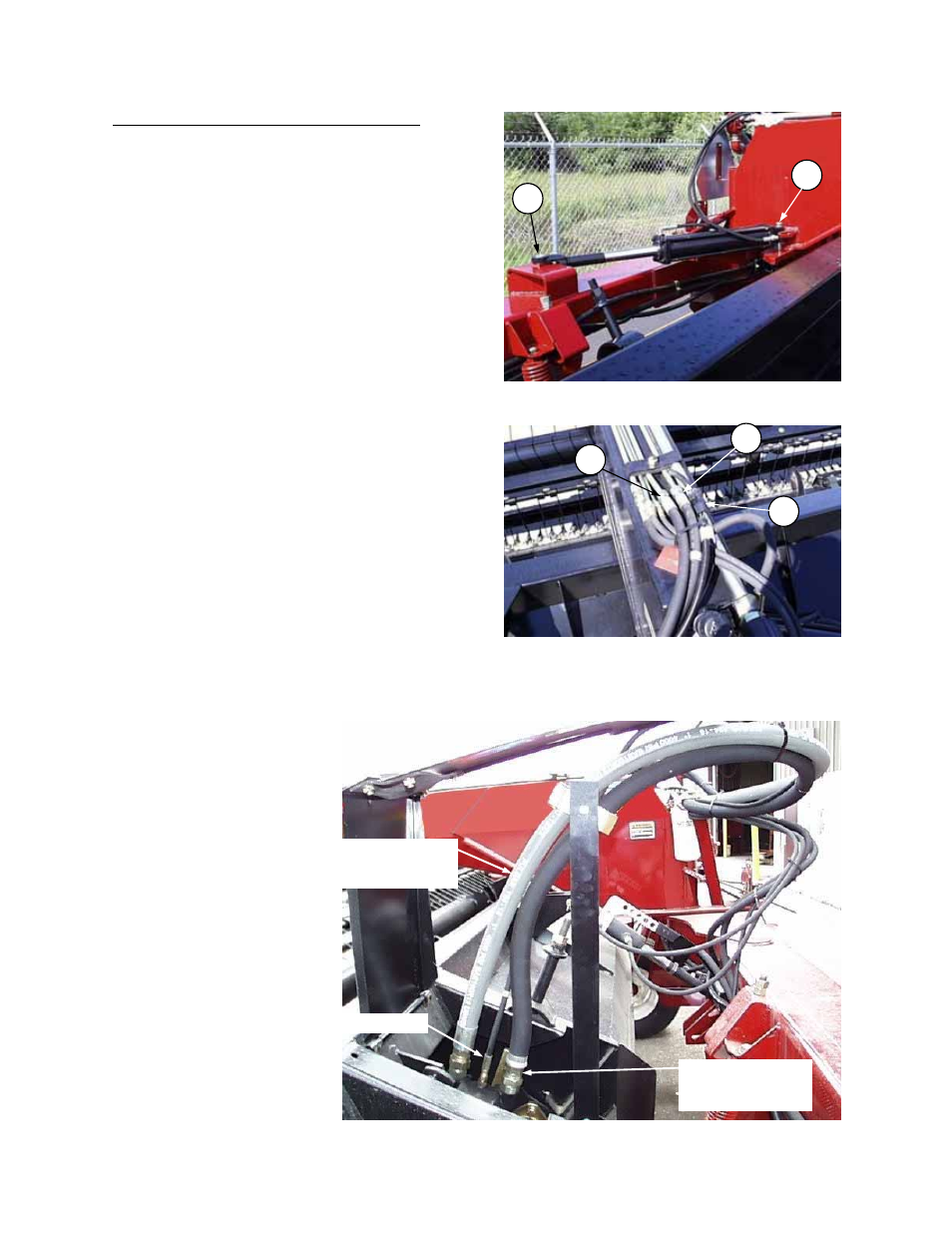
ATTACH HYDRAULICS AND ELECTRICAL
1. Attach barrel end (A) of shift cylinder to
bracket on hitch. Attach rod end (B) to bracket
on frame tube. Secure pins with cotter pins
(installed below brackets).
NOTE: It may be necessary to loosen a hose
fitting to allow extension of cylinder rod. Be
sure to retighten fitting after cylinder
installation.
2. Remove lift cylinder hoses and electrical
harness from shipping position in the upright
hose support near motor. Route hoses and
harness through top clamp (Y) at tongue (see
Step 7). Attach lift cylinder hoses to open
hydraulic lines at (N) and (P) on top of tongue.
NOTE: Connect hose from left lift cylinder
(master) to left hydraulic line, and hose from
right lift cylinder (slave) to right hydraulic line.
Loosen clamp on top of tongue to ease
installation of hoses. Retighten clamp after
attaching hoses.
3. Connect electrical wiring harness at (R).
4. Attach hoses to header drive motor:
NOTE: For additional clearance when installing
hoses, first lower the header if raised.
a. Remove cotter pin securing bottom of motor
shield and open shield.
b. IMPORTANT: To prevent contamination of the
hydraulic system, extreme care must be taken
to avoid dirt entering at hose ends and motor
ports. To minimize
exposure to
contamination, remove
cap from one hose and
its mating motor port
plug and connect before
removing other caps and
plugs. Install hoses in
sequence from front to
rear of motor (pressure –
case drain – return).
Ensure that pressure
and return hoses are
connected to the proper
fitting as shown in photo
at right. Tighten all
hoses securely.
c. Close motor shield and
secure with cotter pin.
INSTALL SHIFT CYLINDER
A
B
ATTACH LIFT HOSES
AND ELECTRICAL HARNESS
N
P
R
RETURN FROM
REAR MOTOR PORT
TO FILTER
PRESSURE FROM
RELIEF VALVE TO
FRONT MOTOR PORT
CASE DRAIN
ATTACH HOSES TO MOTOR