7disc spindles, Disc spindles, Warning – MacDon R85 Rotary Disc 13 Foot Self-Propelled Windrower Header User Manual
Page 140
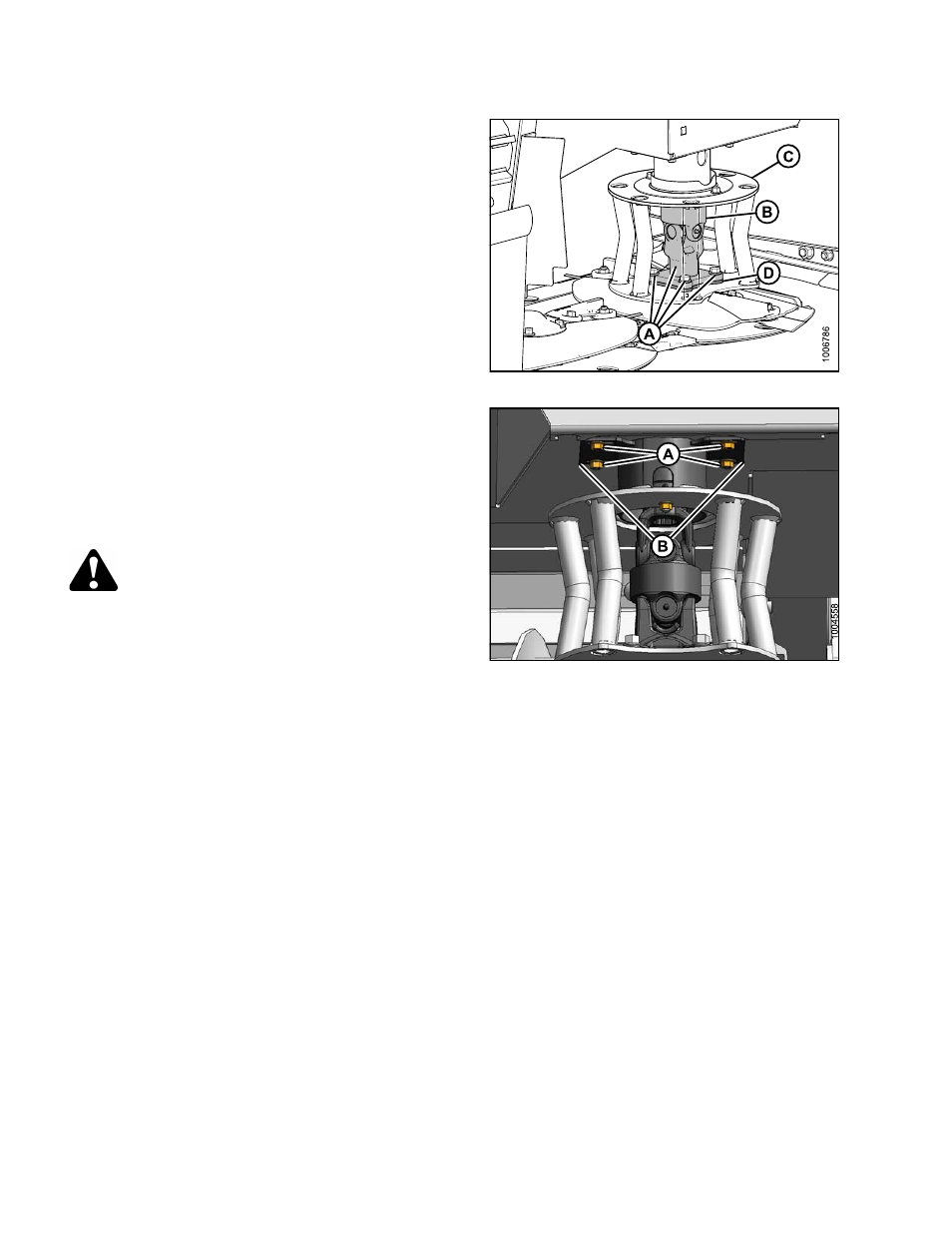
3. Insert spacer (D) onto disc.
4. Insert driveline (B) into deflector (C) and install onto
shaft. Ensure that driveline (B) grease zerks will be
accessible through large opening in deflector.
5. Align mounting holes in deflector (C), spindle, and
driveline (B) and reinstall four bolts (A). Tighten bolts.
6. Adjust the upper driveline shield to achieve consistent
gap around deflector shield (C).
Figure 7.44
7. Tighten bolts (A) on shield plates (B).
8. Remove block of wood (if used).
9. Manually rotate discs to check for interference of
adjacent parts.
10. Close cutterbar doors.
See Section
.
WARNING
Ensure cutterbar is completely clear of foreign
objects.
These objects can be ejected with
considerable
force
when
the
machine
is
started and may result in serious injury or
machine damage.
Figure 7.45
7.6.7
Disc Spindles
To prevent damaging the cutterbar and drive systems, each disc is attached to a spindle which incorporates a key
that shears if the disc contacts a large stone, a stump, or other large object. In the event of a sheared key, the disc
stops rotating, but remains attached to the spindle.
169455
132
Rev. E