Precision Turbo and Engine BigStuff3 GEN3 Powertrain Controller Ignition Setup Tutorial User Manual
Page 9
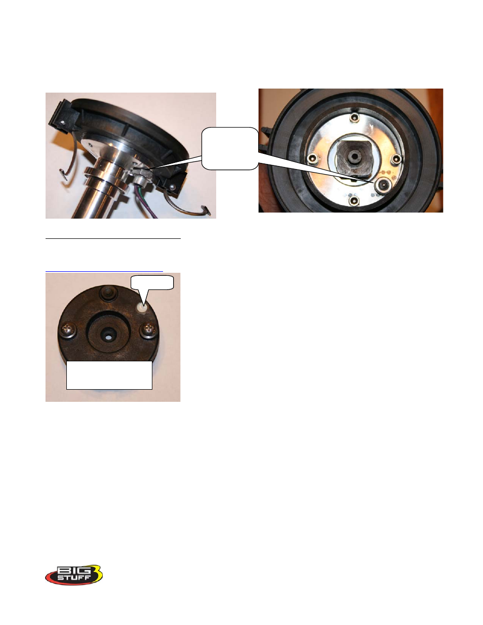
MSD Cam Sync Drive
Shown below is MSD’s cam sync distributor, part number 2340.
Inductive
pick-up
(sensor)
Installing the Cam Sync Distributor
The cam sync (signal) needs to occur 10
o
– 20
o
before the “Crank Reference” angle (see
on page 25 ). For example, if the “Crank Reference” angle is set to
45
o
BTDC (number 1 cylinder, compression stroke), the cam
sync should be installed between 55
o
and 65
o‘s
BTDC.
Magnet
Start by rotating the engine to the desired cam sync position (55 –
65
o
BTDC #1 Comp). Next remove the distributor cap and rotor.
While aligning the magnet with the Inductive Pick-Up (IPU)
sensor, drop it into the engine.
Note: Install the Cam Sync Distributor making sure that it is
installed in the engine in an orientation that allows the plug wires
to be easily routed to their respective cylinders and that the leads
(wires from the pickup) can be easily connected to the main wire
harness. Make sure the distributor is seated fully. “Bump” the engine to engage the oil pump drive.
Once fully seated, rotate the engine back to the desired cam sync position (55 – 65
o
BTDC), then
realign the magnet with the Inductive Pick-Up (IPU) sensor and tighten the base down.
Magnet carrier. Rotor
attaches to this piece
Next you’ll need to check/verify your rotor phase. Rotate the engine now to the timing desired for max
power (20
o
for boosted engines) note where the rotor is in relation to the distributor cap terminal. It
should be directly across. If not, use an MSD adjustable rotor or if space allows, an MSD “Cap-a-
Dapt” to correct the rotor phase. If space does not allow for a “Cap-a-Dapt” or the adjustable rotor did
not provide adequate phasing you will need to reposition the magnet in the magnet carrier as described
below.
8