Ls1_2_wire_sensor_connection – Precision Turbo and Engine BigStuff3 GEN3 Powertrain Controller Ignition Setup Tutorial User Manual
Page 33
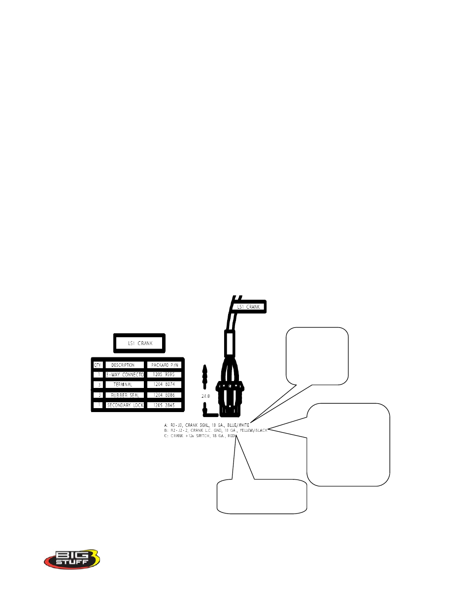
How to Connect the BS3 Two (2) Wire Magnetic Sensor to the BS3 LS1 Main Wire Harness
The LS1 main wire harness was designed to interface with the stock, three wire Hall Effect Device
(HED) sensor. BigStuff3’s 24 tooth wheel and sensor kit uses a two (2) magnetic sensor. The steps,
necessary to modify the LS1 main wire harness to accept the two wire sensor, are outlined below.
Note: Before proceeding, make sure that the BigStuff3 main wire harness is disconnected from
the battery!
As shown below, the LS1 crank sensor connector has three wires. Only the blue/white and
yellow/black wires are going to be used to install the two wire magnetic sensor. The red wire will not
be used. It has a constant 12 Volts being supplied to it and therefore
must be cut, taped and shrink
wrapped!
3M has sells a heat shrink material (EPS 300) with an adhesive lining that BS3 highly
recommends.
Electrical Terminations
• The
purple
sensor wire needs to connect to the BigStuff3
blue
/white wire in the LS1 main wire
harness.
• The
green
sensor wire needs to connect to the BigStuff3
yellow
/
black wire in the LS1 main
wire harness.
• The BigStuff3
yellow
/
black wire in the LS1 main wire harness needs to be moved from header
connector location J3 to header connector location A3.
Connect the
yellow/black wire to
the green sensor
wire. Also, move
this wire from header
location J2 to header
location A3.
Connect the
blue/white
wire to the
purple sensor
wire.
The red wire is not used.
It must be cut, taped and
shrink wrapped
32