Page 22 – Practical Instrument Electronics 830 User Manual
Page 24
Page 22
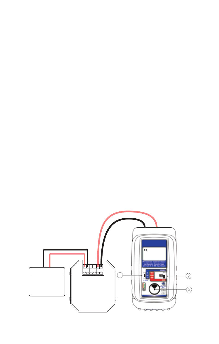
Typical
2-Wire
Transmitter
+ IN - REF +OUT-
Transmitter Input
Sensor
Process Signal
Simulated Input
SOURCE
HI
SET
LO
MAX
READ
MIN
READ
11.999
mA
PWRM
5 6
+ -
Power/Measure mA, Power/Measure % (Percent of 4 to 20 mA)
Choose this function to simultaneously supply power to a 2 Wire
Transmitter while displaying the 4.000 to 20.000 mA output of
the transmitter.
Move the power switch
w
to READ then Double Click the
EZ-DIAL knob to get into the Menu. Turn the knob
e
to scroll
through the settings and press the knob to make your selection.
Select mA for the FUNCTION and PWR MEAS for the MODE.
Choose either mA or % and whether you need the 250
Ω HART
resistor active in the loop.
Disconnect one or both input wires from the device to be
calibrated. Connect the red source lead of the PIE 830 to the
plus (+) input of the device and the black source lead to the
minus (-).
The PIE 830 supplies a nominal 24 volts DC at 24 mA to the 2
Wire Transmitter. The current passed by the transmitter will be
accurately displayed by the PIE 830. Calibrate the transmitter in
the usual manner and disconnect the PIE 830. Signals above 24
mA are current limited by protection circuitry with “OVERRANGE”
flashed on the display and the red OVERLOAD LED lit.