Section 6.b, Section – Pololu Dual MC33926 User Manual
Page 22
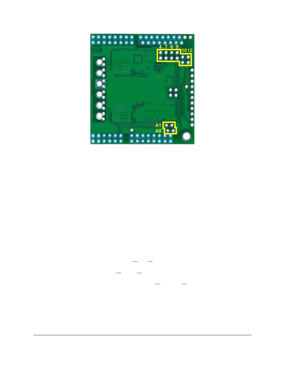
Cuttable traces on the dual MC33926 motor
driver shield for changing default Arduino
connections.
The yellow boxes mark the locations where traces can be cut on the underside of the PCB to remap the default
Arduino pin assignments. The top through-hole of each vertical pair connects to the Arduino pin and the bottom
through-hole connects to the motor driver pin. For the A0 and A1 pairs, which are oriented horizontally, the right
pins connect to the Arduino and the left pins connect to the motor drivers (when the shield is viewed from the top
side). In the figure above, the pin number label is next to the pin that connects directly to the Arduino.
To change one of the default mappings, simply use a knife to cut the trace between the appropriate pair of holes on
the underside of the PCB (there is no connection to cut on the topside of the PCB) and run a wire from a different
Arduino pin to the bottom (or left) hole of the pair to create a new connection. You can later use
to restore the default pin mapping if you populate the severed hole pairs
with 2×1 pieces of the included 0.1″ male header strip.
The pins highlighted in blue in the above diagram are the Arduino header pins and their secondary breakout rows.
These pins are also connected by a single trace on the underside of the PCB, and these traces can also be cut if
you wish to sever the connection between the breakout point and the header pin.
6.b. Accessing nD2 and nSF Pins Separately for Each Channel
The shield combines the two motor driver chips’ D2 and SF pins in order to decrease the number of I/O lines
required to control the motors. The combined lines are sufficient for most applications, but you can modify the
board to get independent access to the MxD2 and MxSF pins if you want the additional control and information.
There are two pairs of 0.1″-spaced holes on the shield labeled “D2 1=2” and “SF 1=2”. These pairs are connected
on the underside of the PCB by a thin trace, with the holes labeled “M1” connecting to the M1 driver and the
holes labeled “M2” connecting to M2 driver.
Pololu Dual MC33926 Motor Driver Shield User's Guide
© 2001–2013 Pololu Corporation
6. Customizing the Shield
Page 22 of 24