Wiring, Connection modules – Paxton PROXIMITY KP series keypad User Manual
Page 2
Switch2 controllers with WHITE labels are incompatible with these products. The keypads in the K and KP series,
can only be used with Switch2 controllers fitted with YELLOW wiring labels.
When using this keypad style with Net2, the software version used must be v3.21 or later.
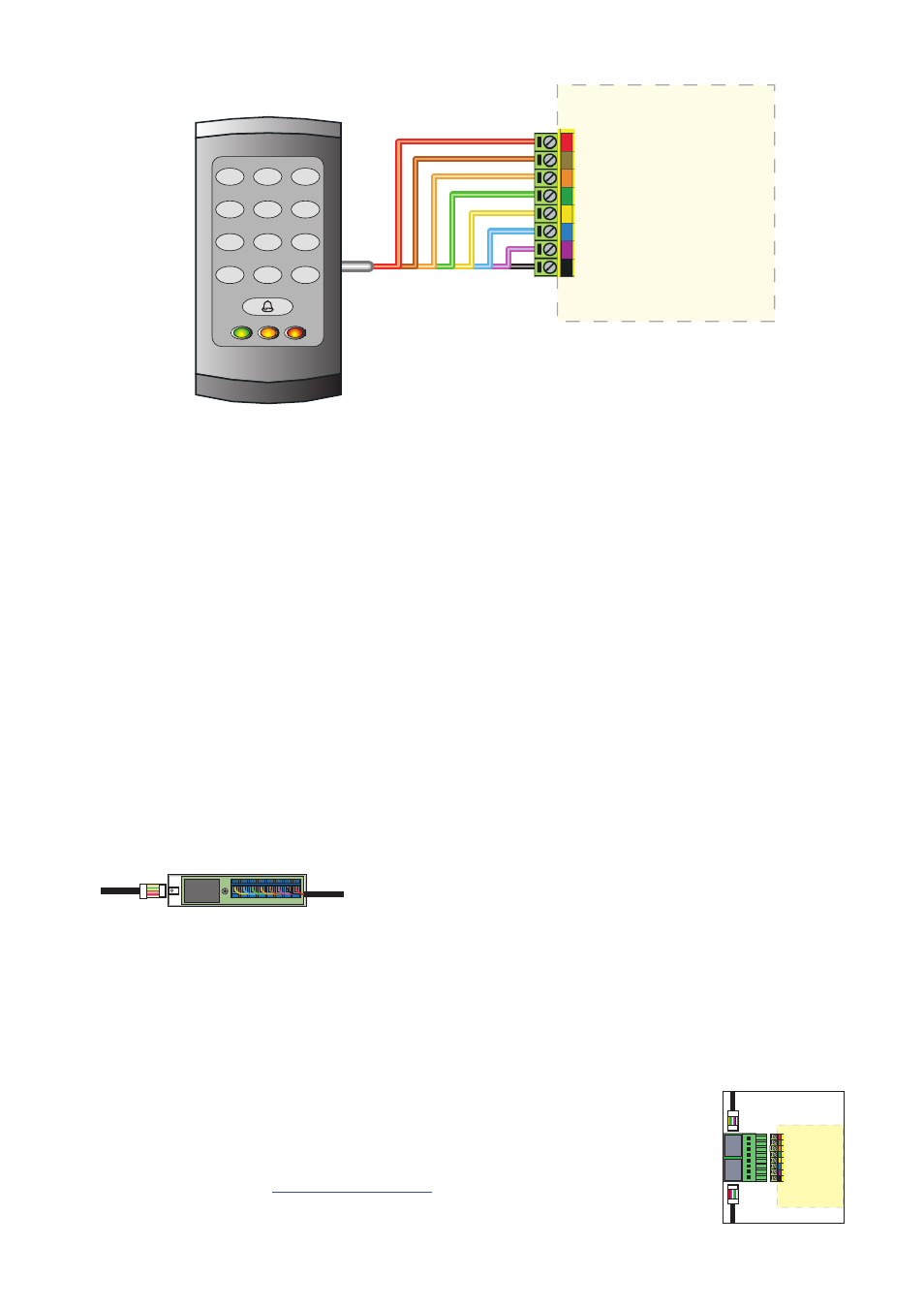
WHITE labelled Net2 control units provide 5V at the Red terminal. The Red power wire for the reader should
therefore be directly connected to the 12V ACU terminal.
1
2
3
4
5
6
7
8
9
0
#
*
Wiring
The reader port module is designed to convert the
standard reader ports on Switch2 and Net2 controllers
to accept one or two RJ45 connections. Pull off the
screw terminal block from the reader port and simply
replace it with this module.
This module can be used to provide a
connection point for the reader RJ45 plug.
The terminals on the module are then wired
colour for colour to the controller.
Alternatively, the reader can be wired directly
into the screw terminals of the control unit by
first cutting off the RJ45 plug and stripping
back the wires in the cable.
Reader port module (325-030)
This module may be purchased separately to speed up
the installation and replacement of readers.
Connection modules
Further information on how to purchase Installer Tools is available at:
http://paxton.info/841
Reader junction box (325-020)
Connection to a control
unit reader port