Paxton BC 402 Compact Card Reader User Manual
Page 2
BC 402 Compact Card Reader
Installation
Doc. No. 016/2
Page 2
BC 402 Compact Card Reader
Configuration
Doc. No. 016/2
Page 3
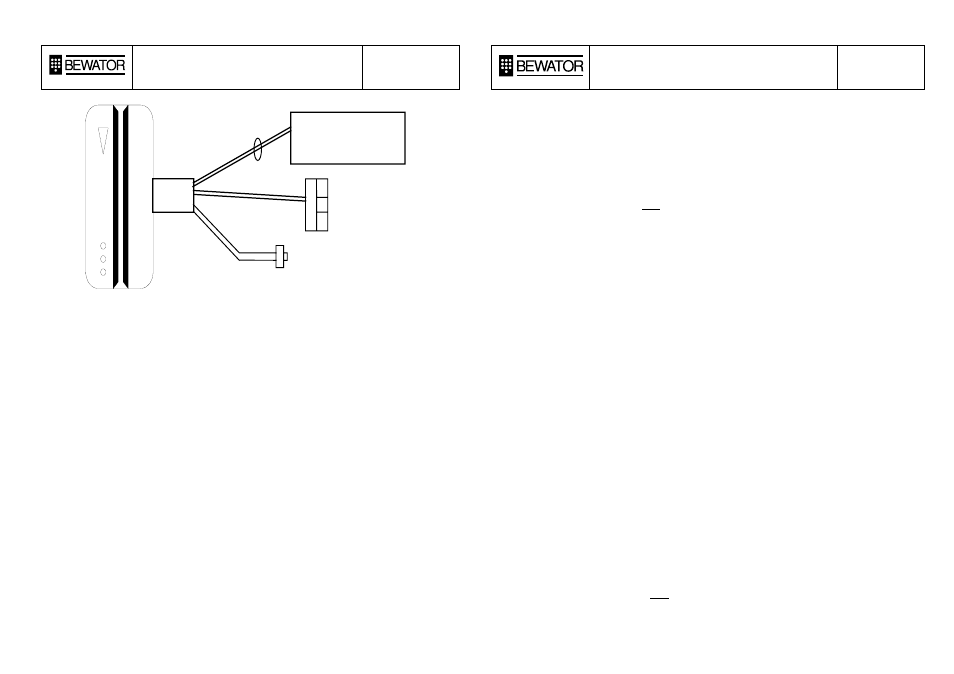
Bewator P.S.U.
173-104
Exit Request
(Push to make)
Blue Exit
Mauve 0v
Yellow 12v
Green 0v
Electric
Lock
Red 12v
Black 0v
Setting up the system.
There are three types of card required to operate the BC 402, they consist of the following;
Control Cards (Plastic)
1) The Master card - This card is used to initialize the unit and set the door release time.
2) Fail Open/Fail Locked Card - This card is used to change the logic of the door output. This card
is linked to the Master Card, so may only be used after initialisation, and only on the reader(s)
initialised with the associated Master Card.
Shadow Cards (Paper)
These are used to issue and delete the User Cards. One shadow card is used for each User card. The
Shadow Cards are also linked to the Master Card
User Cards
The cards that will be used day-to-day by the personnel, these may be standard Bewator IB-1 cards or
even the user's bank or credit card.
Initial Operation
When the BC 402 is first powered up the Green arrow L.E.D will flash, which indicates that the reader
requires initialisation.
At this stage (and this stage only) the BC 402 requires to be initialised with the Master card.
Carefully swipe the Master card once in the reader in a downwards direction.
The arrow L.E.D will go continuously green and the unit will give a confirmation bleep. If the L.E.D
continues to flash, the card has been mis-read.
Setting the Door Output Logic
The reader must now be set according to the type of electric release to be used. This may be either
"Fail Locked" (power to release) or "Fail Open" (power to lock).
After initialisation, the unit is set to "Fail Locked" operation. If "Fail Open" operation is required,
swipe the Fail Open/Fail Locked Card once. This will toggle the operation of the output. Swiping the
card again will return the reader to "Fail Locked" operation
Once this initialisation has been completed the BC 402 is ready for use
Mounting Instructions
The unit is mounted to the wall by means of 2 fixing screws, these screws are then hidden by
fixing the reader cover which is secured by a single screw in the base of the unit.
Mount the reader module to the wall using the 2 fixing screws and wall plugs provided. Use the
reader itself as a template for drilling the holes. A larger hole is required in the centre of the
reader to allow the cable to pass through the wall.
Hook the reader cover over the module mounted to the wall, lower the reader down so that it
covers the reader completely making sure the LED indicators are located correctly in their
respective holes. Secure the cover to the reader at the bottom of the reader cover using the
screw provided.
Technical Specification
Operating Voltage
11 to 16 Volts D.C.
(Bewator TABC Power
Supply
No. 173-104)
Quiescent Current
80 mA
Lock Output
MOSFET 1000 mA maximum at supply voltage ( DC )
Operating Temperature
-20 to +55 Centigrade
Measurement
89 * 34 * 34 mm
Environmental rating
IP *7