Warning – Bryant 355CAV User Manual
Page 26
26
Table 4 – Electrical Data
UNIT SIZE
VOLTS---
HERTZ---
PHASE
OPERATING VOLTAGE
RANGE
MAXIMUM
UNIT
AMPS
MINIMUM
WIRE SIZE
MAXIMUM
WIRE
LENGTH
FT (M)}
MAXIMUM
FUSE OR CKT
BKR
AMPS**
Maximum*
Minimum*
060---14/042060
115---60---1
127
104
8.96
14
30 (9.1)
15
080---14/042080
115---60---1
127
104
8.96
14
30 (9.1)
15
080---20/060080
115---60---1
127
104
14.06
12
31 (9.4)
20
100---20/060100
115---60---1
127
104
14.06
12
31 (9.4)
20
120---20/060120
115---60---1
127
104
14.06
12
31 (9.4)
20
* Permissible limits of voltage range at which unit will operate satisfactorily.
{
Unit ampacity = 125 percent of largest operating component’s full load
amps plus 100 percent of all other potential operating components’ (EAC,
humidifier, etc.) full load amps.
}
Length shown is as measured 1 way along wire path between unit and
service panel for maximum 2 percent voltage drop.
** Time---delay type is recommended.
ELECTRICAL SHOCK AND FIRE HAZARD
Failure to follow this warning could result in electrical
shock, fire, or death.
The cabinet MUST have an uninterrupted or unbroken
ground according to NEC ANSI/NFPA 70--2008 and
Canadian Electrical Code CSA C22.1 or local codes to
minimize personal injury if an electrical fault should occur.
This may consist of electrical wire or conduit approved for
electrical ground when installed in accordance with existing
electrical codes. Do not use gas piping as an electrical
ground.
!
WARNING
COPPER
WIRE ONLY
ELECTRIC
DISCONNECT
SWITCH
ALUMINUM
WIRE
A93033
Fig. 30 -- Disconnect Switch and Furnace
Install power entry hole filler plugs (factory--supplied in loose parts
bag) in unused power entry holes. (See Fig. 31.)
FACTORY
INSTALLED
LOCATION
UNUSED 7/8-IN. (22 mm)
DIAMETER POWER
ENTRY HOLES
POWER ENTRY HOLE
FILLER PLUG (FACTORY-
SUPPLIED LOOSE PARTS BAG)
A05113
Fig. 31 -- Factory Installed J--Box Location
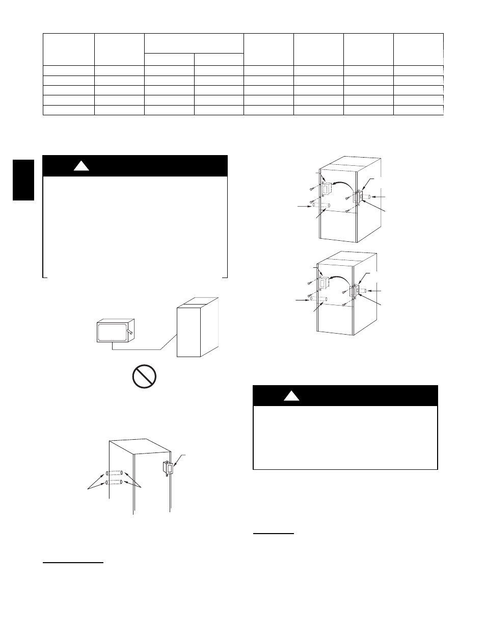
J--Box Relocation
1. Remove two screws holding auxiliary J--box. (See Fig. 32.)
2. Rotate J--box 180_ and attach box to left side, using holes
provided.
FACTORY
INSTALLED
LOCATION
ALTERNATE
FIELD
LOCATION
POWER ENTRY HOLE
FILLER PLUG (FACTORY-
SUPPLIED LOOSE PARTS BAG)
UNUSED 7/8-IN. DIAMETER
POWER ENTRY HOLES
UNUSED 7/8-IN. DIAMETER
POWER ENTRY HOLES
POWER ENTRY HOLE
FILLER PLUG (FACTORY-
SUPPLIED LOOSE PARTS BAG)
FACTORY
INSTALLED
LOCATION
ALTERNATE
FIELD
LOCATION
POWER ENTRY HOLE
FILLER PLUG (FACTORY-
SUPPLIED LOOSE PARTS BAG)
UNUSED 7/8-IN. (22 mm) DIAMETER
POWER ENTRY HOLES
UNUSED 7/8-IN. (22 mm) DIAMETER
POWER ENTRY HOLES
POWER ENTRY HOLE
FILLER PLUG (FACTORY-
SUPPLIED LOOSE PARTS BAG)
A05058
Fig. 32 -- J--Box Relocation
3. Install power entry hole filler plugs (factory--supplied loose
parts bag) in unused power entry holes. (See Fig. 31.)
FIRE OR ELECTRICAL SHOCK HAZARD
Failure to follow this warning could result in personal
injury, death, or property damage.
If manual disconnect switch is to be mounted on furnace,
select a location where a drill or fastener will not contact
electrical or gas components.
!
WARNING
NOTE:
If modulating dampers are used, blower motor
automatically compensates for modulating dampers. If manual
disconnect switch is to be mounted on furnace, select a location
where a drill or fastener will not contact electrical or gas
components.
24--v wiring
Make field 24--v thermostat connections at 24--v terminal block on
furnace control. Y wire from thermostat MUST be connected to
Y/Y2 terminal on control, as shown in Fig. 19, for proper cooling
operation. The 24--v terminal block is marked for easy connection
of field wiring. (See Fig. 33.) The 24--v circuit contains a 3--amp,
automotive--type fuse located on furnace control. (See Fig. 33.)
355C
A
V
355C
A
V