Warning – Bryant 355CAV User Manual
Page 25
25
Electrical Connections
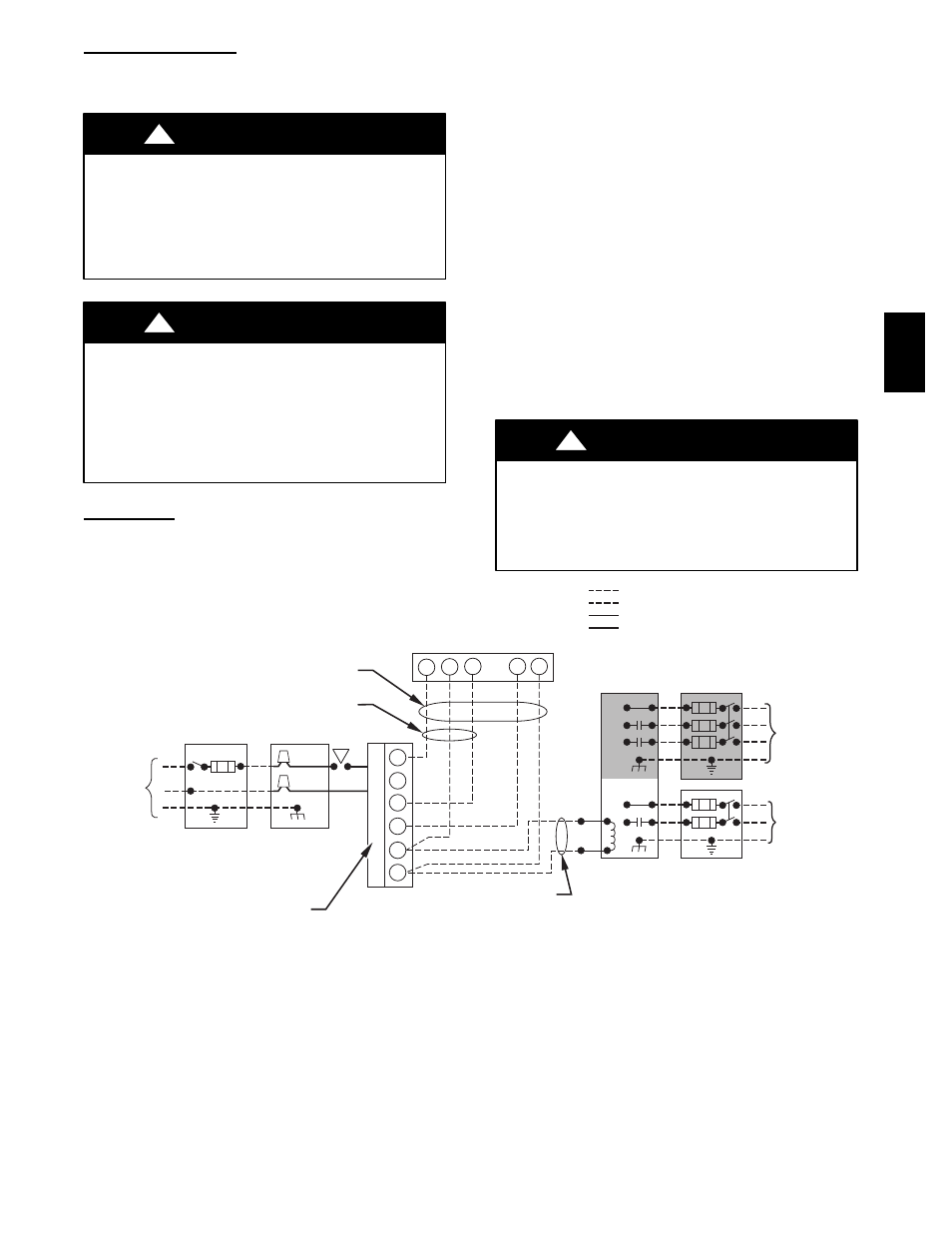
See Fig. 29 for field wiring diagram showing typical field 115--v
and 24--v wiring. Check all factory and field electrical connections
for tightness.
ELECTRICAL SHOCK HAZARD
Failure to follow this warning could result in personal
injury or death.
Blower access door switch opens 115--v power to furnace
control. No component operation can occur. Do not bypass
or close switch with panel removed.
!
WARNING
UNIT MAY NOT OPERATE
Failure to follow this caution may result in intermittent
unit operation.
Furnace control must be grounded for proper operation
or control will lock out. Control is grounded through
green/yellow wire connected to gas valve and burner
box screw.
!
WARNING
115--v Wiring
Before proceeding with electrical connections, make certain that
voltage, frequency, and phase correspond to that specified on
furnace rating plate. Also, check to be sure that service provided by
power supply is sufficient to handle load imposed by this
equipment. Refer to rating plate or Table 4 for equipment electrical
specifications.
Make all electrical connections in accordance with National
Electrical Code (NEC) ANSI/NFPA 70--2008 and any local codes
or ordinances that might apply. For Canadian installations, all
electrical connections must be made in accordance with Canadian
Electrical Code CSA C22.1 or authorities having jurisdiction.
Field--supplied wiring shall conform with the limitations of 63_F
(33_C) rise.
The furnace must be electrically grounded in accordance with local
codes; or in the absence of local codes, with the National Electric
Code ANSI/NFPA 70 and/or the Canadian Electric Code, CSA
C22.1, Part I, if an external electrical source is utilized.
Use a separate branch electrical circuit containing a properly sized
fuse or circuit breaker for this furnace. See Table 4 for wire size
and fuse specifications. A disconnecting means must be located
within sight from and readily accessible to furnace.
NOTE: Proper polarity must be maintained for 115--v wiring. If
polarity is incorrect or furnace is not grounded properly, furnace
control status code indicator light will flash rapidly and furnace
will NOT operate.
FIRE HAZARD
Failure to follow this warning could result in personal injury,
death, or property damage.
Do not connect aluminum wire between disconnect switch
and furnace. Use only copper wire. (See Fig. 30.)
!
WARNING
115-V
FIELD-SUPPLIED
DISCONNECT
SWITCH
115-V
SINGLE
PHASE
AUXILIARY
J-BOX
FURNACE
CONTROL
CENTER
TWO WIRE
24-V
TERMINAL
BLOCK
THREE-WIRE
HEATING
ONLY
FIVE
WIRE
NOTE 5
NOTE 1
NOTE
3
THERMOSTAT
TERMINALS
FIELD-SUPPLIED
DISCONNECT
CONDENSING
UNIT
R
W2
W
C
R
G
Y
GND
GND
GND
GND
FIELD 24-V WIRING
FIELD 115-, 208/230-, 460-V WIRING
FACTORY 24-V WIRING
FACTORY 115-, 208/230-, 460-V WIRING
208/230- OR
460-V
THREE PHASE
208/230-V
SINGLE
PHASE
W/W1
Y/Y2
G
C
NOTES:
1.
2.
3.
4.
5.
Connect Y or Y/Y2 terminal as shown for proper cooling operation.
Proper polarity must be maintained for 115-v wiring.
Use W2 with 2-stage thermostat when zoning.
If any of the original wire, as supplied, must be replaced, use
same type or equivalent wire.
Some thermostats require a "C" terminal connection as shown.
A98325
Fig. 29 -- Heating and Cooling Application Wiring Diagram
355C
A
V
355C
A
V