Dca-85ssju — generator start-up procedure – Multiquip DCA85SSJU User Manual
Page 49
DCA-85SSJU — PARTS AND OPERATION MANUAL— REV. #2 (12/21/01) — PAGE 49
DCA-85SSJU — GENERATOR START-UP PROCEDURE
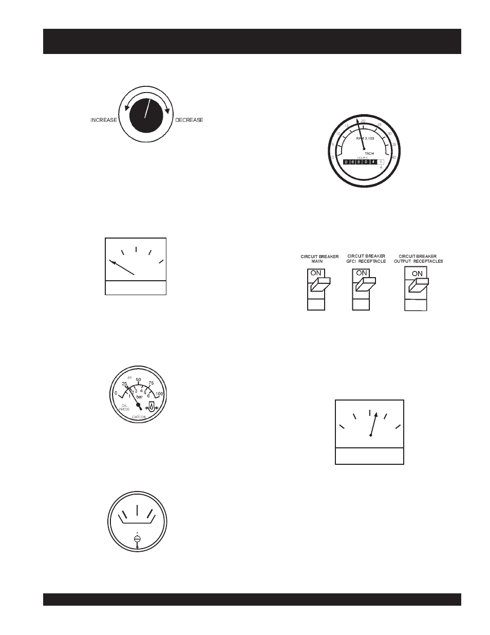
Figure 54. Voltage Adjust Control Knob
Figure 58. Engine Tachometer
15. The tachometer (Figure 58) will indicate the speed of
the engine when the generator is operating. Under normal
operating conditions this speed is approximately 1800
RPM’s.
Figure 59. Main and GFCI Circuit Breakers
16. Turn the MAIN, GFCI and LOAD circuit breakers to
their ON position (Figure 59).
A
0
40
60
75
20
Figure 55. Ammeter (No Load)
12. The ammeter (Figure 55) will indicate zero amps with no
load applied. When a load is applied, this meter will
indicate the amount of current that the load is drawing
from the generator’s alternator.
13. The engine oil pressure gauge (Figure 56) will indicate
the oil pressure (kg/ cm
2
)
of the engine. Under normal
operating conditions the oil pressure is approximately
25 psi.
14. The coolant temperature gauge (Figure 57) will indicate
the coolant temperature. Under normal operating
conditions the coolant temperature is between 165 and
215 degrees Fahrenheit.
WATER
TEMP
Figure 57. Coolant Temperature Gauge
Figure 56. Oil Pressure Gauge
17. Observe the generator's ammeter (Figure 60) and verify
it reads the anticipated amount of current with respect
to the load. The ammeter will only display a current
reading if the load is in use.
18. The generator will run until manually stopped or an
abnormal condition occurs.
A
0
40
60
75
20
Figure 60. Ammeter (Load)