Components – Multiquip C10PH8 User Manual
Page 15
C10SH8-PH8 CONCRETE MIXER • OPERATION AND PARTS MANUAL — REV. #0 (03/06/09) — PAGE 15
COMPONENTS
Major Components
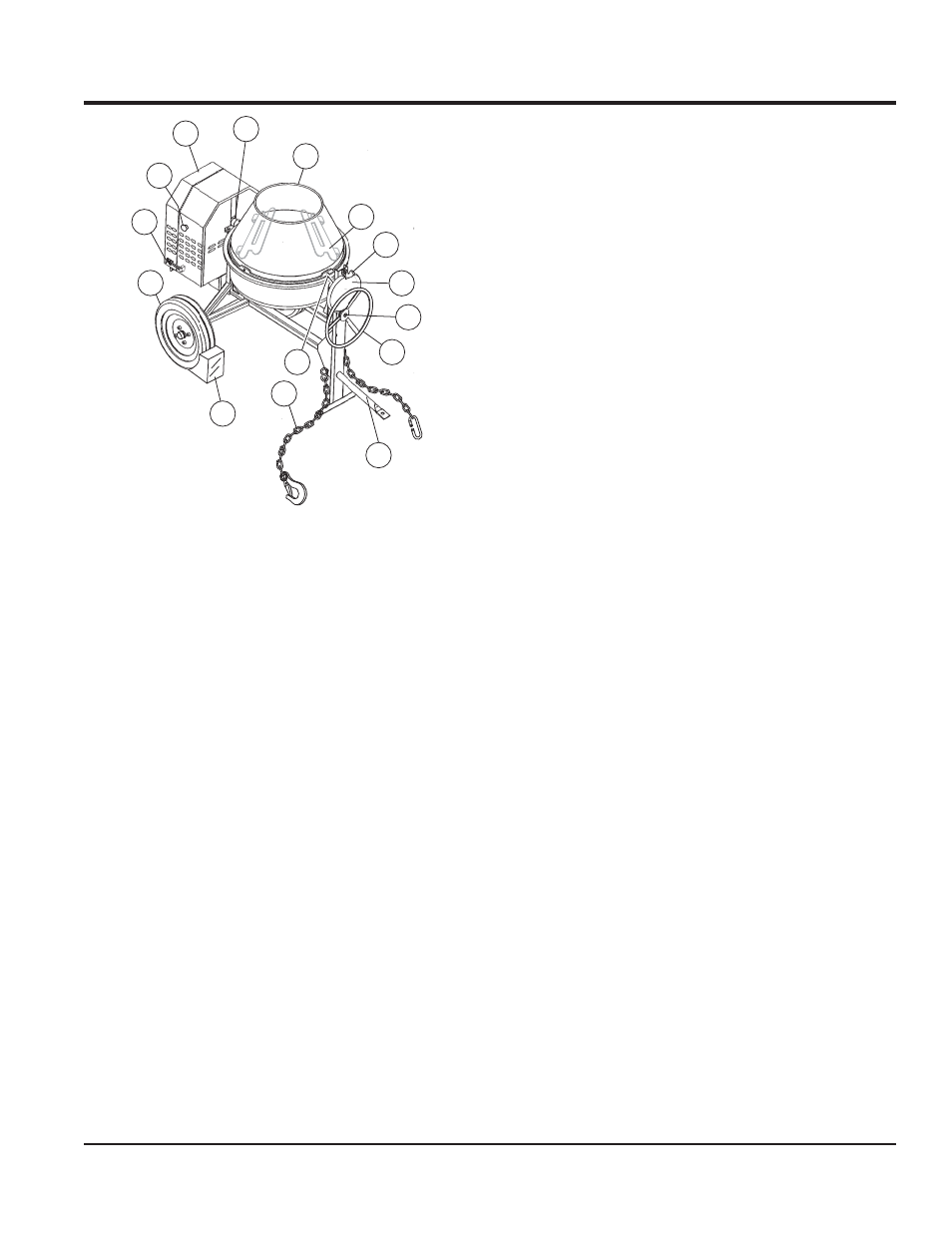
Figure 2.
Figures 2 shows the location of the controls and components
for the C10SH8-PH8 mixer. The function of each control is
described below.
Handwheel
1.
— Turn this wheel clockwise or counter-
clockwise to rotate the mixing drum. Remember the
dump latch must be in the up position in order for the
mixing drum to be rotated.
Dump Gear Guard
2. —
NEVER operate the mixer with
this guard removed. Its purpose is to prevent dirt and
debris from entering the dump gear. In addition operator
clothing could become entangled in the dump gear,
causing severe injury and bodily harm.
Dump Latch
3.
— To rotate the mixing drum, this latch
must be in the up position. To lock the drum, place the
latch in the down position.
Mixing Blades (Steel or Plastic)
4.
— Used for the
mixing of concrete. Replace plastic blades when they
show signs of wear. When steel blades show signs
of wear, entire steel mixing drum assembly must be
replaced. See steel and plastic mixing drum assemblies
in the parts section of this manual.
10
9
11
1
4
5
2
3
7
6
8
12
13
6
6
Mixing Drum
5.
— The C10SH8 uses a 6 cu. ft steel
mixing drum and the C10PH8 uses a 6 cu. ft. plastic
mixing drum. This drum is to be used for mixing of
concrete. Always clean the drum after each use. DO
NOT use this mixing drum for the mixing of volatile
liquids.
Zerk Fittings
6.
— There are three zerk fi ttings on the
mixer that lubricate the handwheel, gear and yoke.
Lubricate fi ttings as referenced in the maintenance
section of this manual.
Engine Cabinet
7.
— Encloses engine. NEVER run mixer
with cabinet removed.
ON/OFF Switch
8.
— This switch is located on the side
of the mixer frame. When activated it will shut down the
engine. Pull out when starting the engine.
Cabinet Latch
9.
— Use latches to secure engine
cabinet.
Tire Ply
10.
— The tire ply (layers) number is rated in
letters; This mixer uses 13-inch 2-ply tires. Replace
with only recommended type tires.
Chock Blocks
11.
— Place these blocks (not included as
part of the mixer package) under each mixer wheel
to prevent rolling when mixer is not connected to the
towing vehicle.
Safety Chain
12.
— This mixer uses a 3/16-inch thick,
72-inches long zinc-plated saftey chain. ALWAYS
connect the safety chain when towing.
Tow Bar
13.
— This mixer uses various towing bars. Please
reference the frame assembly drawing and parts list
in this manual to determine which tow bar meets your
requirements