Daw-500s — controls and indicators – Multiquip DAW500S User Manual
Page 14
PAGE 14 —DAW-500S WELDER/A.C. GENERATOR— PARTS & OPERATION MANUAL — REV. #0 (07/19/01)
DAW-500S — CONTROLS AND INDICATORS
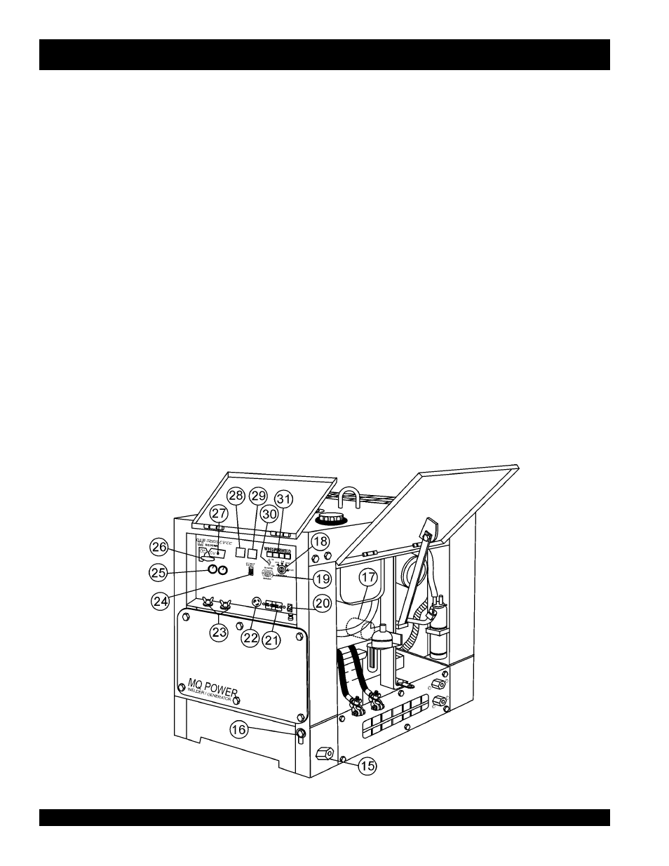
15. Fuel Drain Plug – Remove this plug to drain fuel from the
fuel tank.
16. Frame Ground Lug – Connect a ground strap between
this lug and a ground rod. Make sure the ground rod is
inserted deep into the ground to provide a good earth
ground. Consult with local Electrical and Safety Codes for
proper connection.
17. Oil Filter – Provides oil filtering for the engine.
18. Ignition Switch – With key inserted turn clockwise to start
engine.
19. Hour Meter – Indicates number of hours machine has
been in use or hours engine was run.
20. Circuit Protector Circuit Breaker – This single pole circuit
breaker provides circuit protection (120V @20 amps) for
the G.F.C.I. receptacle.
21. Receptacle G.F.C.I. – This receptacle provides 120 volts
output at 20 amps.
22. Receptacle – Provides 120 volts output at 25 amps.
23. Welding Output Terminals – Connect the welding cable
to this terminal. Select the appropriate polarities according
to the application. See Table 7.
! Low Oil Pressure
! High Water Temperature
! Electrical System Is Not Charging Properly
! Preheat Indicator
27. Sub-Selector Switch-This switch is used to select type of
welding and welding voltage needed. This switch will not
work in CC mode.
28. DC Voltmeter- Indicated the amount of voltage used during
welding in CV mode.
29. DC Ammeter- Indicates the amount of amperage being
used during welding in CC mode.
30. Idle Control Switch – Regulates the engine speed when
the welder/AC generator is under load.
31. Warning Lamp Display – Lights red when the following
conditions occur:
Figure 3. Controls and Indicators (con't)
24. Main Circuit Breaker – This single-pole circuit breaker
provides circuit protection (125V @25 amps) for the electric
parts assembly.
25. Current Control (CC) Voltage Control (CV) Adjustment
Knobs – Use these controls to adjust welding current and
voltage.
26. Welding Type (Wire/Stick) Selector Switch (CV/CC) –
Turn this selector switch to either the CV or CC for welding.
DO NOT turn this switch under load.