MTS SWIFT 45 GLP Sensor User Manual
Page 45
Road and Track Vehicles
SWIFT
®
45 GLP Sensors
Installation
45
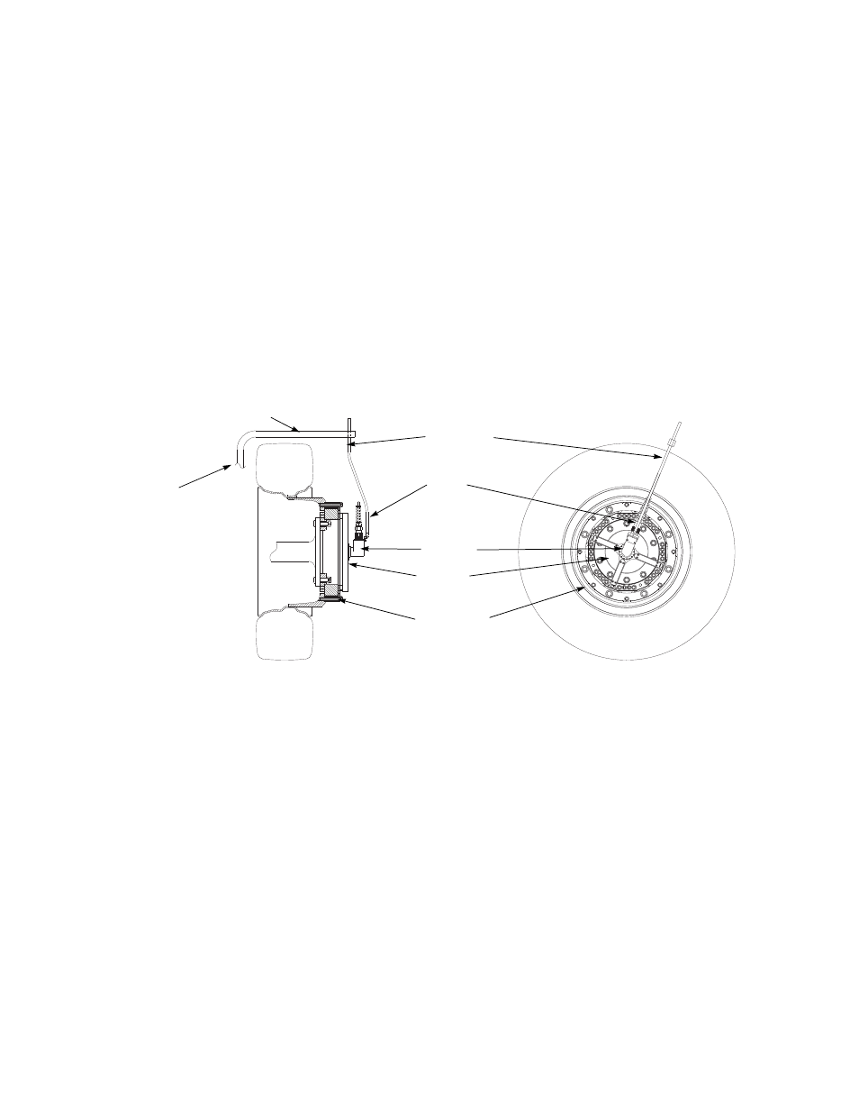
6. For front rim configurations (see the next figure): Attach the slip-ring
bracket with the slip ring, conduit bracket, and restraint tube to the
transducer.
A.
The slip-ring bracket fits over the circular connectors on the front of
the transducer at the four locations. The slip-ring bracket is similarly
labeled to prevent connecting it the wrong way.
Note
Use care when installing the slip-ring bracket. The circular connectors
are keyed. The slip-ring bracket should be fitted on straight (without
bending or angling it) to make sure it engages all four connectors
simultaneously and evenly.
B.
Lubricate the threads and under the bolt heads of the eight
M5 X 0.8 mm bolts with Molykote g-n paste. Insert them through the
mounting hole in the slip-ring bracket and thread them into the
transducer. Torque each to 6.8 N·m (5 lbf·ft).
7. For dual rim configurations (see the next figure): Attach the extension
assembly and slip-ring bracket with slip ring to the transducer.
A.
Thread the standoffs, with the M12 threaded studs, into the four M12
threaded holes in the face of the transducer.
Lubricate the threads on each threaded stud with Molykote g-n paste
and torque to 93 N·m (69 lbf·ft).
B.
Attach the four extension brackets.
C.
Place the top plate, with extensions attached, over the standoffs.
Orient the top plate such that the Board 1 extension (see the labeling
on the top plate) is aligned with the Board 1 connector on the
transducer.
Anti-rotate
assembly
Cable
conduit
bracket
Slip ring
Slip ring
bracket
Transducer
Anti-rotate bracket
(customer supplied)
For front or
steering axles,
anti-rotate arm
must be
mounted to a
part of the
unsprung
suspension
that steers with
the tire, such
as the brake
caliper.