MTS Model 286-30 Pore Pressure Intensifier User Manual
Page 14
286.30 Pressure Intensifier
14
Overview of Typical Pore Pressure Intensifier System
Introduction
Overview of Typical Pore Pressure
Intensifier System
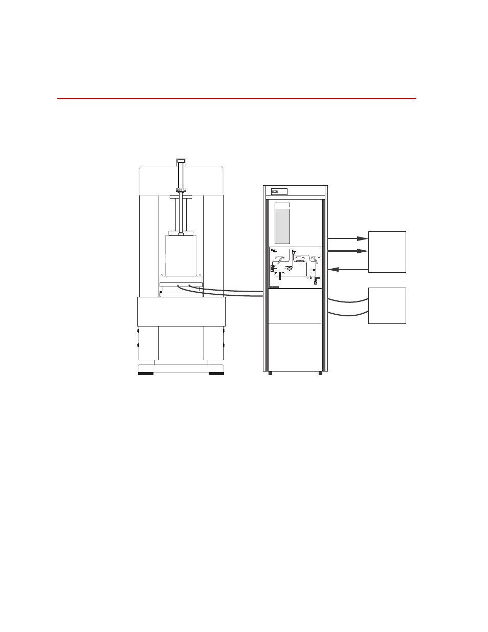
The major system components typically used with the Pore Pressure Intensifier
are shown below.
As shown in the figure, a separate hydraulic power supply acts as the primary
power source for the Pore Pressure Intensifier. Hydraulic fluid pressures up to
21 MPa (3,000 psi) are translated into pore fluid pressures up to 140 MPa
(20,000 psi) under servo control provided by separate electronic controller
equipment.
Pressure and displacement transducers in the PPI provide signals proportional to
their respective variables, enabling the external electronic controller equipment
to measure these variables and to control either the pressure produced by the PPI,
or the linear displacement of the pressure intensifier’s piston relative to a fixed
reference.
While the displacement transducer output signal is proportional to the
displacement of the pressure intensifier’s piston, relative to a reference point, the
electronic control equipment associated with this transducer is usually calibrated
in units of displacement.
Pore Pressure
Instensifier
(PPI)
815
Triaxial
Cell
High
Pressure
Hoses
Typical Load Frame
(rear view)
Pressure
Return
*Feedback Signals
Electronic
Controller
Equipment
Hydraulic
Power
Supply
Displacement*
Pressure*
286.30_001