MTS Series 505G2 SilentFlo Hydraulic Power Unit Model 505G2-30 User Manual
Page 36
Model 505G2.20 - 505G2.30 SilentFlo™ HPU
36
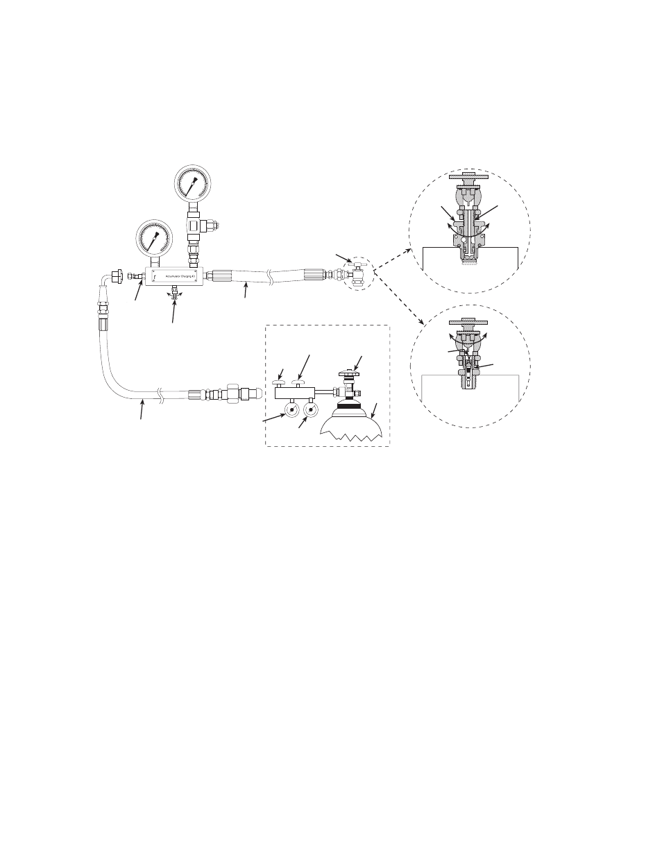
Precharging the Surge Suppressor Accumulator
Installation
Checking the
precharge pressure
The nitrogen precharge should be about 50–60% of the output pressure. Monitor
the pressure gage. If the pressure reading is outside the range of 10.3–12.5 MPa
(1500–1800 psi), perform the procedure “Changing the precharge pressure.”
Charging Kit
Changing the
precharge pressure
The nitrogen precharge should be within the range of 10.3–12.5 MPa (1500–
1800 psi) which is 50–60% of the output pressure (21 MPa or 3000 psi). Perform
one of the following procedures to change the precharge pressure:
Decreasing pressure
To decrease the precharge pressure:
1. Slowly open the bleed valve on the charging kit until gas begins to escape.
When the pressure reading on the appropriate pressure gage drops to the
level required, close the bleed valve.
2. Close the locknut. Open the bleed valve on the accumulator charging kit and
remove the chuck valve from the accumulator.
3. Install the valve stem cap and protective cover.
Increasing pressure
To increase the precharge pressure:
1. Close the locknut on the accumulator.
2. Open the bleed valve two turns.
High Pressure Gage
0–21 MPa (0–3000 psi)
Gage Protector
(factory set to limit
pressure to the
gage to
Extension
Bleed
Input
Nitrogen Supply
Regulator
Nitrogen
Core-Type Valve
To Open and Close
Nitroge
Nitrogen
Bottle
Regulator
Output
Regulator
Shut-Off
You must supply these
Check
Locknu
Valve
Ope
Clos
Poppet-Type Valve
To Open and Close
Close
Valve
Valve
Open
Open
Clos
Low Pressure Gage
0–2.1 MPa (0–300